
 English
 русский
 Español
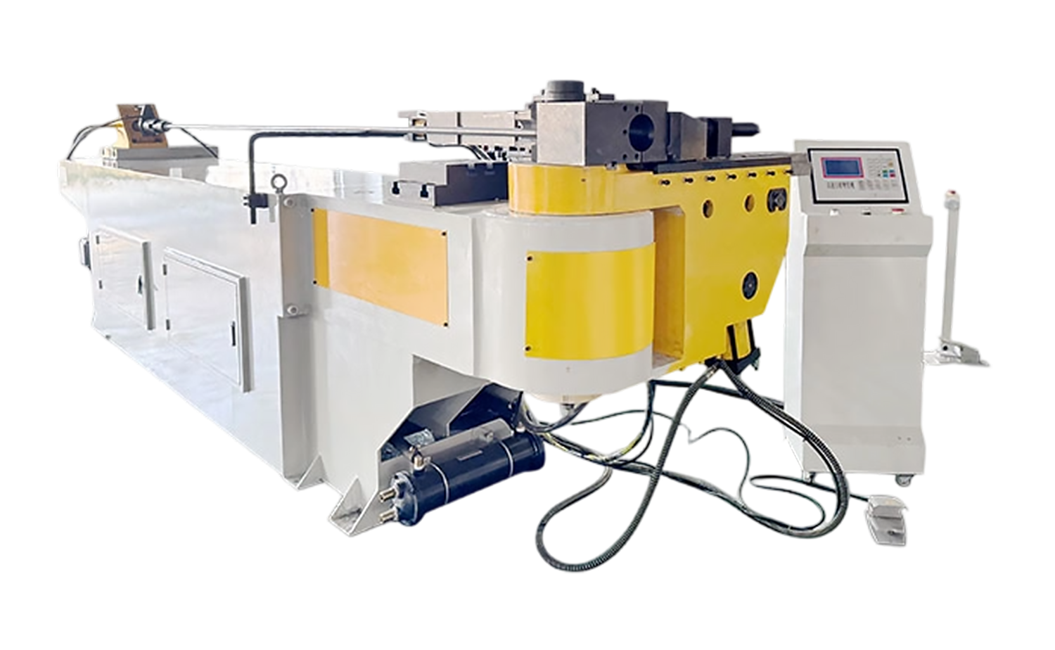
- NC S Series Mandrel Hydraulic Tube Bender with Easy-Program Setting
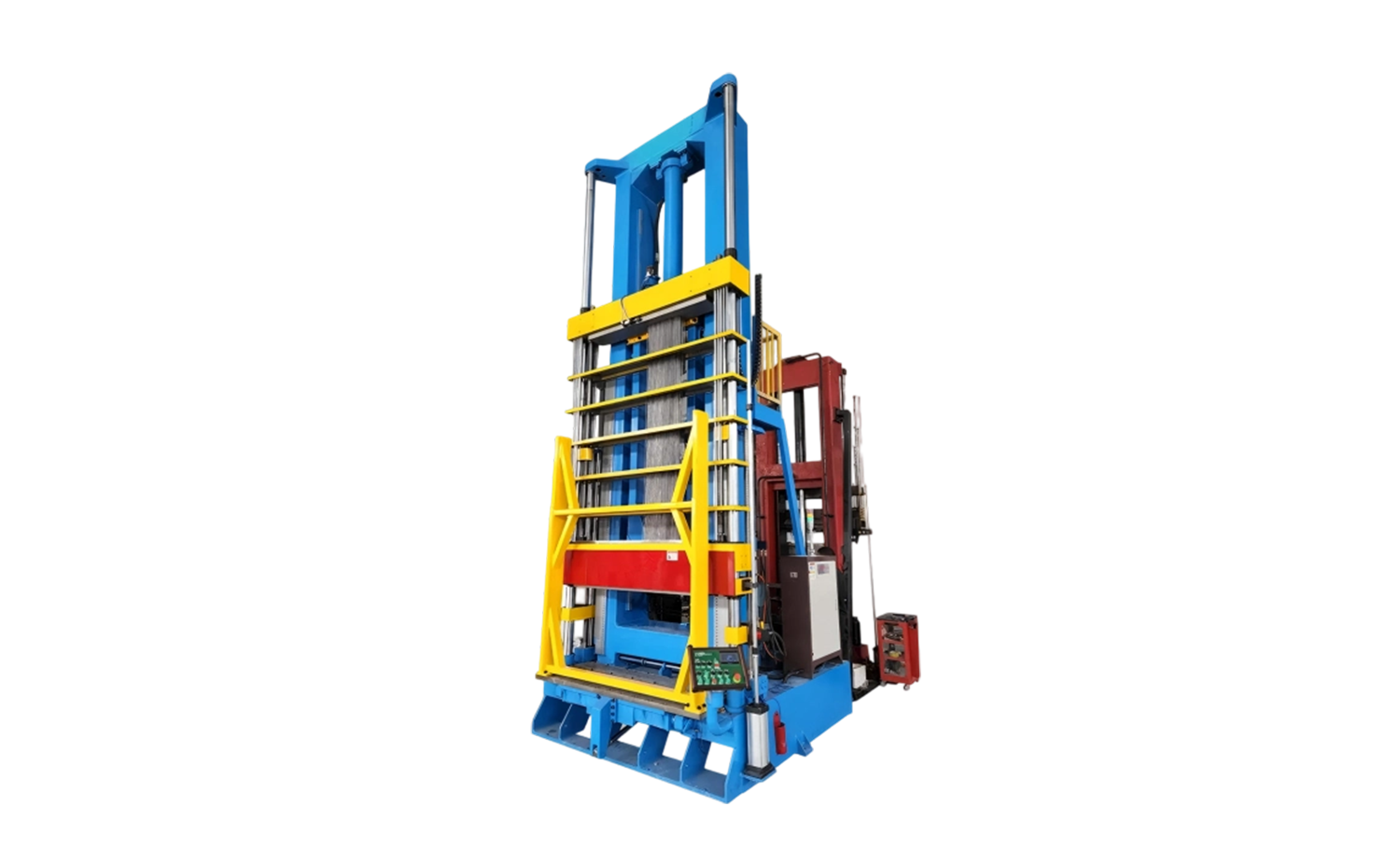
- Quick Changeover Vertical Tube Expanding Machine
- NC M Series Hydraulic Tube Bending Machine with Mandrel Control
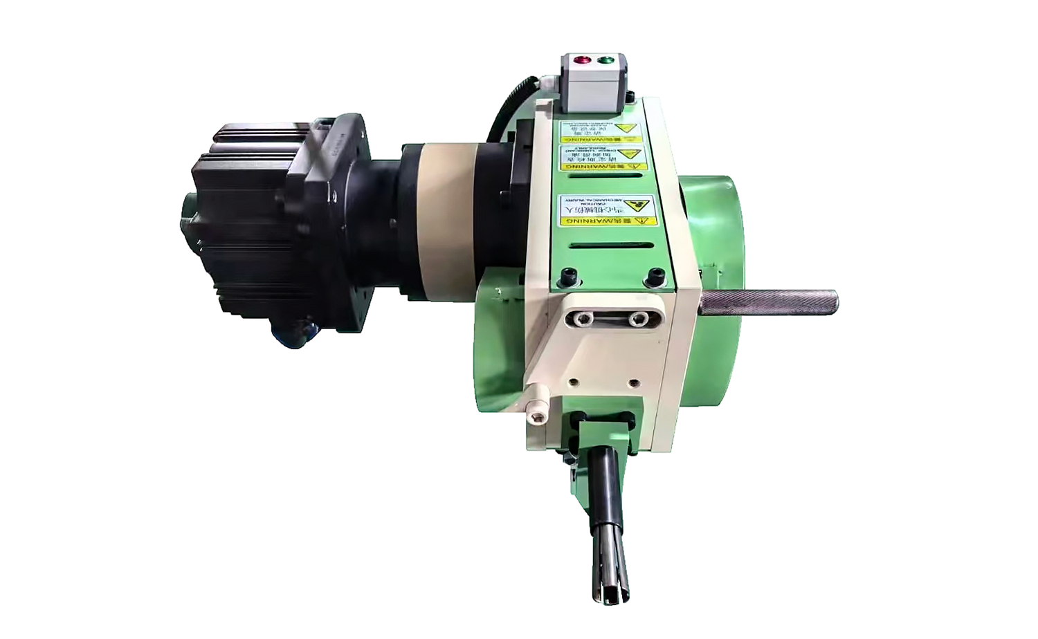
- Adjustabe Handheld Tube Expanding Machine
- SC-30 Chipless Tube Straightening and Cutting Machine
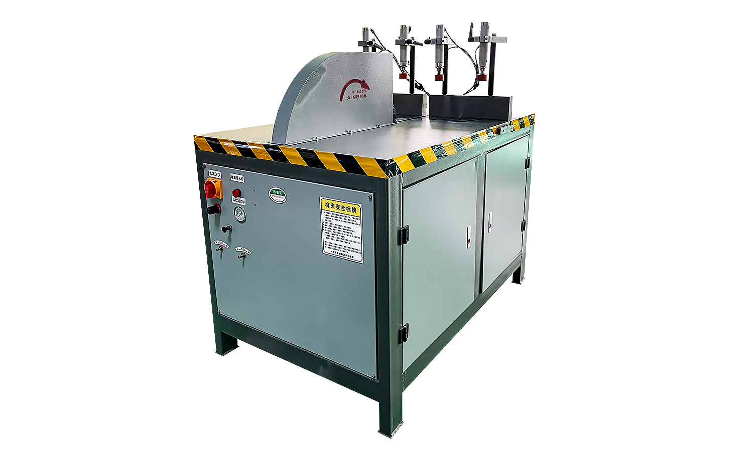
- ES550 Semi-Automatic Aluminum Cutting Machine for Big Profiles and Tubes
Tubing Wall Thickness Chart: Standard Gauges, Inch and Metric Tube Sizes
Date:Oct 02, 2026
Content
- 1 How to Read a Tubing Wall Thickness Chart
- 2 Tubing Wall Thickness Chart in Inch, Metric and Gauge Values
- 3 Tube or Pipe: Two Different Ways to State a Wall
- 4 Tolerances: The Number Behind the Number
- 5 What Wall Thickness Means for Tube Bending
- 6 What Wall Thickness Means for Cutting
- 7 What Wall Thickness Means for End Forming and Chamfering
- 8 Bringing Chart Values to the Machine Builder
Ask anyone who bends, cuts or forms metal tube for a living which single number causes the most surprises on a new job, and wall thickness is usually near the top of the list. It decides whether a bend needs a mandrel, whether a saw blade grabs, and how much a punched hole distorts. A tubing wall thickness chart is really just a translation table: it turns the gauge number or fractional callout on a drawing into a decimal inch or millimeter value that a machine, a die and a tool can actually work with.
What follows is the chart we reach for most often, together with notes on tube versus pipe conventions, mill tolerances, and what each wall range means further down the line.
How to Read a Tubing Wall Thickness Chart
Wall thickness appears in three different languages, and mixing them up is the most common source of scrap.
- Gauge numbers, such as 16 ga, come from the steel wire gauge and are still common on North American drawings for carbon and stainless tube.
- Decimal or fractional inches, such as 0.065 in or 1/16 in, are the shop floor standard for ordering and for setting up tooling.
- Metric millimeters, such as 1.5 mm or 2.0 mm, dominate European and Asian drawings and most ISO based specifications.
Two rules keep the conversions honest. First, gauge numbers are material specific: a 16 gauge aluminum tube and a 16 gauge steel tube are not the same wall. Second, wall thickness and schedule are not interchangeable, and neither one equals inside diameter. The relationship that ties everything together is simple: inside diameter equals outside diameter minus two times the wall.
Tubing Wall Thickness Chart in Inch, Metric and Gauge Values
The table below lists the wall thicknesses that appear most often on tube drawings, with the nearest steel gauge equivalent and the kind of work each wall usually suits.
| Wall (inch) | Wall (mm) | Steel gauge (approx.) | Typical use |
|---|---|---|---|
| 0.028 | 0.71 | 22 | Instrument and capillary tubing, light decorative frames |
| 0.035 | 0.89 | 20 | Brake lines, small hydraulic lines, cable conduit |
| 0.049 | 1.24 | 18 | Fuel and air lines, light frames, handlebars |
| 0.065 | 1.65 | 16 | General fabrication, guards, small welded frames |
| 0.083 | 2.11 | 14 | Roll cages, brackets, furniture and fitness frames |
| 0.109 | 2.77 | 12 | Chassis parts, medium structural tube |
| 0.120 | 3.05 | 11 | Heavy frames, agricultural implements |
| 0.134 | 3.40 | 10 | Machine bases, load bearing structures |
| 0.165 | 4.19 | 8 | Pressure service, heavy structural columns |
| 0.250 | 6.35 | — | Heavy wall sleeves, machined bushings and spacers |
Metric tube is normally ordered in round steps, such as 1.0, 1.2, 1.5, 2.0, 2.5, 3.0 and 4.0 mm, rather than in gauge. Pipe takes a third route and is described by nominal size plus schedule, which is why a chart alone rarely settles a pipe question.
Tube or Pipe: Two Different Ways to State a Wall
Pipe is sized by nominal bore, NPS in North America and DN in metric practice, while the wall comes from the schedule. Under ASME B36.10M, NPS 2 pipe has a 60.3 mm outside diameter in every schedule, but the wall moves from 2.77 mm in Schedule 10 to 3.91 mm in Schedule 40 and 5.54 mm in Schedule 80. A two inch tube, by contrast, is 50.8 mm OD and is ordered as OD by wall, for example 50.8 x 1.5 mm.
That difference matters at the machine. Grooving tools, threading heads and pipe fittings are built around pipe OD and schedule, while bending dies, mandrels and collets are built around tube OD and wall. Copper tubing for HVAC and refrigeration follows the tube convention, quoted as outside diameter with a wall such as 0.040 in, and it behaves very differently from a steel pipe of similar outside diameter.
Tolerances: The Number Behind the Number
A chart value is nominal. Delivered tube can be thinner or thicker within the limits of the governing standard, and that spread is what breaks setups. Cold drawn welded stainless tube to ASTM A269 or A249 commonly carries a wall tolerance of plus or minus 10 percent, while seamless product is often allowed plus or minus 12.5 percent. European precision tube under EN 10305-1 is quoted by tolerance class, with the tighter classes holding closer limits.
Worth checking rather than trusting the label:
- Use a micrometer with a ball or spherical anvil on curved tube; a flat anvil bridges the curve and reads low.
- Use an ultrasonic thickness gauge for large diameters or when you need to confirm a material certificate.
- Measure at four points at 90 degree intervals and at both ends of the piece, then again after the first bend if the wall is thin.
Eccentricity and ovality hide inside a single wall callout. A tube that measures 2.0 mm across the top of the section may measure 1.7 mm near the weld seam, and that is exactly where a bend will fail.
What Wall Thickness Means for Tube Bending
Bending is where wall thickness shows its temper. A practical rule of thumb is the ratio of wall to outside diameter:
- Wall at 5 percent of OD or thicker: a straightforward draw bend is often possible with simple tooling.
- Wall between 2 and 5 percent of OD: plan on a mandrel and watch the inside radius for wrinkles.
- Wall below 2 percent of OD: expect a mandrel plus a wiper die, and consider boost or roll bending instead of draw bending.
Thin wall also increases springback, because there is less material holding the formed shape, so overbend values need adjusting. Thick wall pushes the other way with more torque, faster tool wear and a larger minimum radius for a given die set. In automotive manufacturing, where several of these wall ranges can appear on one assembly, repeatable mandrel positioning and multi radius tooling save a great deal of setup time.
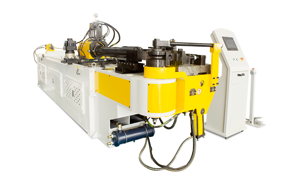 CNC M Series Fully Automatic Multi-Radius Tube Bending MachineFor automotive assemblies needing multiple wall ranges, this multi-radius CNC bender offers servo feeding, rotation, mandrel lubrication, and touch-screen PLC control.View Product →
What Wall Thickness Means for Cutting
Thin wall tube is the classic saw killer: teeth catch, the tube deflects, and the burr ends up worse than the cut. Chipless cutting with servo controlled feeding handles light walls cleanly because the material is separated by controlled deformation rather than by a toothed blade, and it leaves a face that needs little or no deburring. Laser cutting simply ignores wall thickness once the parameters are set, which is why it suits thin wall, high mix production. For heavy wall, a hydraulic or pneumatic circular saw with solid clamping is still the fastest economical choice.
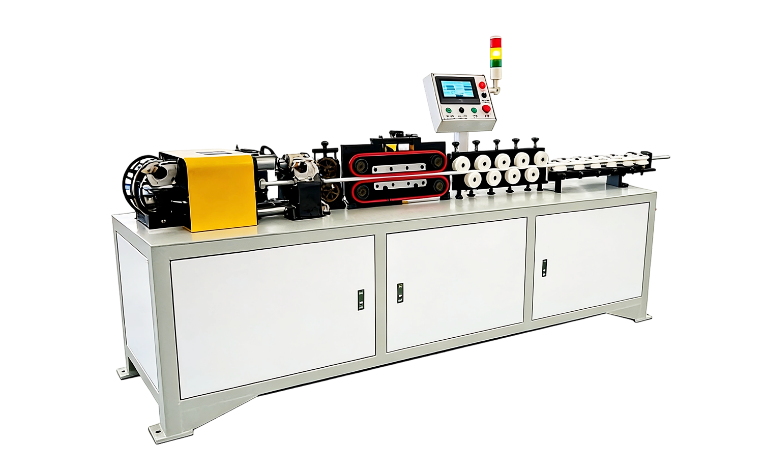 SC-30 Chipless Tube Straightening and Cutting MachineFor copper and aluminum tube processing, this chipless straightening and cutting machine uses rotary cutting and clamping to minimize distortion and deliver clean ends.View Product →
What Wall Thickness Means for End Forming and Chamfering
Expanding, reducing, flaring and sealing all put the wall into tension or compression. Thin wall wrinkles or splits, while heavy wall demands more force and a stiffer frame. Chamfering is more forgiving, but the wall sets the maximum chamfer length and the blade geometry, and a wall that varies around the circumference produces an uneven land. The sequence of operations deserves a moment of thought as well: when a heavy wall end form meets a light wall bend, forming the end first gives the collet and mandrel more material to grip, whereas a tight end form close to a bend is often finished after bending to avoid disturbing the bent geometry.
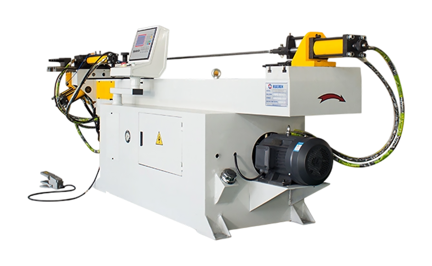
 TM60 Hydraulic Single Head Tube End Forming MachineFor end forming operations such as expanding, reducing, flaring, and custom shapes, this hydraulic single-head machine offers PLC touch-screen control and quick die changes.View Product →
Bringing Chart Values to the Machine Builder
Almost every question about bending, cutting or end forming tooling can be answered faster when four numbers arrive together: outside diameter, wall thickness, material and the smallest centerline radius required. Add the tolerance class if one is called out, plus the batch quantity. With those values in hand, the wall thickness chart stops being a reference page and becomes a specification that selects the mandrel, the die, the blade and the clamping pressure.
If a drawing shows only a gauge number, convert it to decimal inch or millimeters and confirm the gauge system with the mill or the customer first. It is a five minute email that prevents a scrapped batch, and if you would like a second opinion on the tooling that suits a particular wall, our engineers are glad to read the drawing with you.



Copyright © 2025 Huashun Technology All Rights Reserved.
Custom Precision Tube Forming Machine Manufacturers