
 English
 русский
 Español
- NC M Series Hydraulic Tube Bending Machine with Mandrel Control
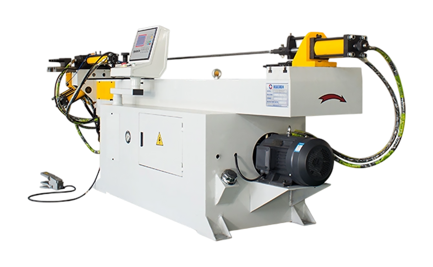
- NC S Series Mandrel Hydraulic Tube Bender with Easy-Program Setting
- CNC S Series Fully Automatic Tube Bending Machine with Optional Simulation Function
- CNC M Series Fully Automatic Multi-Radius Tube Bending Machine
- CNC L Series Fully Automatic Tube Bending Machine with Servo-Hydraulic Control
- NC L Series High-performance Hydraulic Pipe/Tube Bending Machine
Tube Bending Formulas: Developed Length, Bend Deduction and Springback
Date:Sep 11, 2026
Content
Tube bending formulas are not academic exercises. They are the reason a fabricated part drops into the fixture the first time, and the reason a length of tube gets cut correctly before anyone touches the saw. Whether you are working from an LRA (line, radius, angle) print or a table of XYZ coordinates, the same handful of relationships keeps coming back: developed length, setback, bend deduction, and the corrections that account for what the material actually does under load. Here is the working set we rely on every day, along with the places where the math stops and experience has to take over.
Define the Geometry Before You Calculate Anything
Most calculation errors start with a single ambiguity: which dimension does the radius refer to? On a tube drawing, the radius is normally given to the centerline of the tube, called the centerline radius or CLR, not to the inside of the bend. If a print quotes an inside radius, add half the outside diameter before you touch any formula below. Mixing the two up by 25 mm on a 50 mm tube throws the developed length off by roughly 39 mm on a 90-degree bend, which is more than enough to scrap the part.
A second convention matters just as much: bend angle versus degrees of bend. A bend that turns the tube through a right angle is 90 degrees of bend, and the included angle between the two legs is also 90 degrees in that case. When the tube folds back toward itself, the included angle shrinks while the degrees of bend grows, because DOB = 180 degrees minus the included angle. Confirm which value the drawing is quoting before you build a setup around it.
| Symbol | Meaning | Typical unit |
|---|---|---|
| CLR | Centerline radius of the bend | mm or in |
| OD | Outside diameter of the tube | mm or in |
| t | Wall thickness | mm or in |
| DOB | Degrees of bend, equal to 180 minus the included angle | degrees |
| DL | Developed length of one bend | mm or in |
| SB | Setback from the leg intersection to the tangent point | mm or in |
| BD | Bend deduction | mm or in |
| K | Neutral-axis shift factor used to refine arc length | unitless |
The Core Formulas
Developed Length, Also Called Arc Length
The developed length is the amount of tube consumed by the curve itself, measured along the centerline:
DL = (pi × CLR × DOB) / 180
For a CLR of 150 mm and 90 degrees of bend, DL = (3.1416 × 150 × 90) / 180 = 235.6 mm. Some shops refine this with a neutral-axis factor, because material flows toward the inside of the bend during forming and the true neutral line shifts slightly inward: DL = (pi × DOB / 180) × (CLR minus K × t). The factor K usually lands between 0.2 and 0.5, and the only honest way to fix it for your material is to bend a test piece and measure it.
Setback and Tangent Length
Setback is the distance from the intersection point of the two leg centerlines back to the tangent point, where the straight leg ends and the curve begins:
SB = CLR × tan(DOB / 2)
At 90 degrees, tan(45 degrees) equals 1, so the setback equals the CLR, which is 150 mm in our example. Tangent length is the same number measured from the intersection point along each leg, which makes it easy to convert between a drawing that dimensions to intersections and one that dimensions to tangents.
Bend Deduction
When a drawing gives leg lengths measured to the intersection points, the corner is counted twice. Bend deduction removes that overlap:
BD = 2 × SB minus DL
For the 90-degree example: 2 × 150 minus 235.6 = 64.4 mm. For shallow bends the deduction is small; for tight, high-angle bends it becomes large enough that ignoring it guarantees a short part.
Total Cut Length
Cut length = sum of leg lengths measured to intersection points, minus the sum of all bend deductions. The equivalent route is cut length = sum of straight tangent-to-tangent sections, plus the sum of developed lengths. Both methods should agree. When they do not, the usual cause is a bend that was forgotten in the subtraction.
Offsets and Distance Between Bends
For a pair of equal bends that shift a tube sideways by a distance O, the distance between bends measured along the tube is DBB = O / sin(DOB). A familiar 45-degree offset therefore multiplies the offset by roughly 1.414. For unequal angles, or for anything happening in three dimensions, work in coordinates rather than trying to chain two-dimensional formulas together.
What the Formulas Do Not Cover: Wall Thinning, Ovality and Minimum Radius
Everything above assumes the tube keeps its shape. It does not. The outside of the bend stretches and thins, the inside compresses and thickens, and the cross-section flattens slightly. These effects decide whether a theoretically correct part is actually manufacturable.
Wall Thinning on the Outside of the Bend
A useful thin-wall estimate is t_min = t × CLR / (CLR + OD / 2). For a 50 mm OD tube with a 2 mm wall on a 150 mm radius, that gives roughly a 14 percent reduction. Treat this as a conservative geometric limit rather than a measured result. With a properly sized mandrel, correct clearance and appropriate boost, real thinning is usually noticeably less.
Ovality
Ovality is calculated as (D_max minus D_min) divided by OD, multiplied by 100. General industrial work often accepts 5 percent or less, while aerospace and automotive fluid lines frequently demand tighter limits. Ovality grows quickly as the CLR-to-OD ratio falls, which is why the radius choice and the tooling choice are really the same decision.
Minimum Bend Radius Rules of Thumb
- Free-form bending without a mandrel: roughly 3 × OD is a practical floor for many mild steels and aluminums.
- With a mandrel and wiper die: 1.5 × OD is routine, and 1 × OD or tighter is achievable with matched tooling and a heavier wall.
- Wall factor (OD divided by t) above about 30 usually makes thin-wall collapse the limiting factor rather than the radius itself.
- Stainless and high-strength alloys need more radius or more support than carbon steel at the same wall factor.
A Worked Example: 90-Degree Bend in 50 mm OD Tube
Put the formulas together for a common job: 50 mm OD, 2 mm wall, 150 mm centerline radius, 90 degrees of bend, with two straight legs of 400 mm measured to the intersection points.
| Quantity | Formula | Result |
|---|---|---|
| Developed length | (pi × 150 × 90) / 180 | 235.6 mm |
| Setback per end | 150 × tan(45 degrees) | 150.0 mm |
| Bend deduction | 2 × 150 minus 235.6 | 64.4 mm |
| Cut length | 800 minus 64.4 | 735.6 mm |
| Estimated wall thinning | 2 × 150 / (150 + 25) | 1.71 mm, about 14 percent thinner |
The thinning figure is the geometric worst case for an unsupported bend. If your specification caps wall thinning at 10 percent, you would open up the radius, add a mandrel with the right clearance, or move to a heavier wall before cutting any material.
From Formula to Finished Part
Numbers get you a drawing; tooling and control repeat that drawing a thousand times. Springback is the clearest example. After the tooling releases, the tube relaxes and the bend opens slightly, so the machine has to overbend and the radius grows a little relative to the tool. Mild steel at a 3 × OD radius might need only one or two degrees of overbend, while stainless and high-strength aluminum can need considerably more. The practical answer is not a better equation but a control that stores compensation values per material, per radius and per wall thickness, then applies them automatically on the next run.
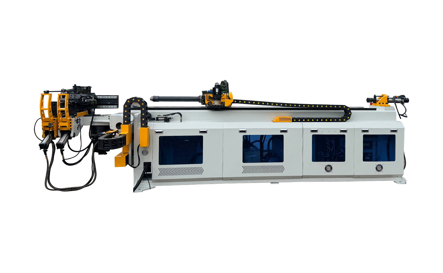
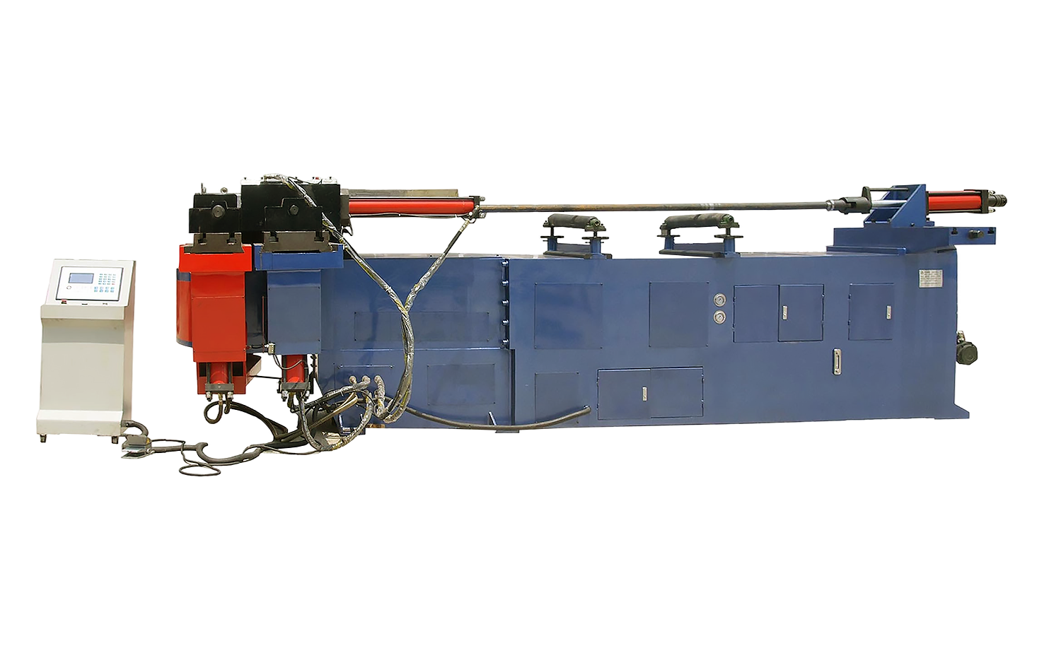
That is the point where formulas and equipment have to agree. A machine that can position the bend, hold the mandrel and follow the boost curve exactly as the setup sheet specifies turns your calculated numbers into a repeatable process rather than a one-off success. If you are working through the same calculations across different part families, it helps to see the range of tube bending machines side by side, from manual and NC models to fully automatic CNC units.
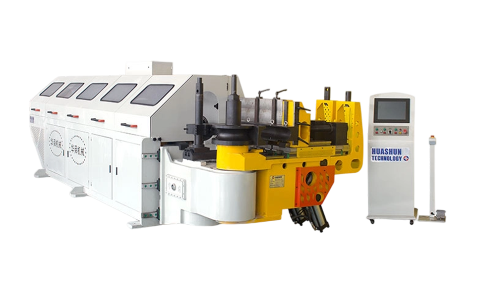 CNC L Series Fully Automatic Servo-Hydraulic Tube Bending MachineFor repeatable calculated bend setups, model SB-219CNC offers three programmable axes, servo feeding and rotation, hydraulic and CNC bending modes, and mandrel lubrication.View Product →
Multi-radius parts deserve a separate mention here. When one tube carries several bends at different radii, the developed length has to be calculated bend by bend, and each bend needs its own setback and deduction. The arithmetic is identical, but the setup is not, and machines built for multi-radius work remove a lot of the trial and error from that job.
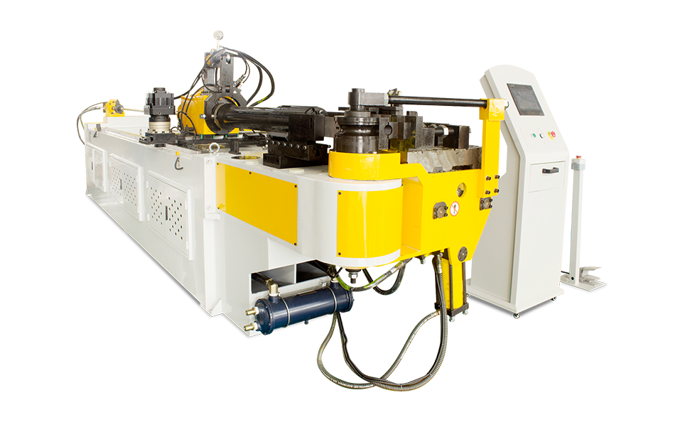 CNC M Series Fully Automatic Multi-Radius Tube Bending MachineFor multi-radius tube work, model SB-75CNC provides three programmable axes, hydraulic and servo CNC bending, mandrel lubrication, and touch screen PLC control.View Product →
Thin-wall tubes with a wall factor above 25 or 30 push the geometry hard, and that is where mandrel support stops being optional. A mandrel-controlled bender lets you fine-tune mandrel position and lubricant flow, which is often the difference between a 14 percent thinning estimate and a part that passes inspection. For high-volume work in sectors such as automotive manufacturing, that repeatability matters more than a slightly lower machine price.
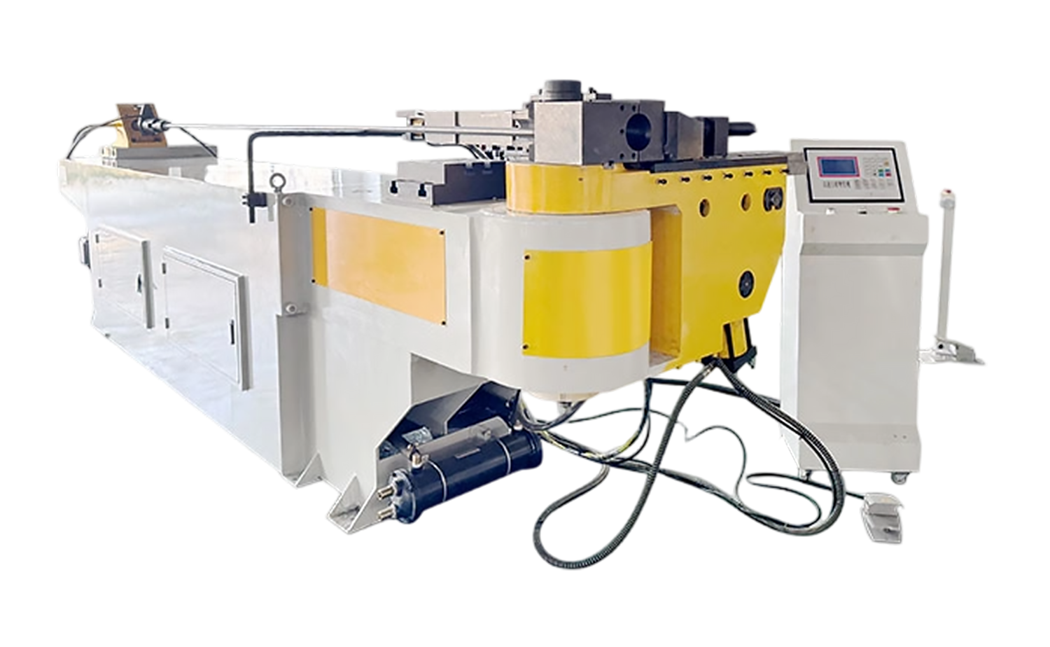 NC M Series Hydraulic Tube Bending Machine with Mandrel ControlFor repeatable bends across steel, stainless, aluminum, titanium, and brass, this semi-automatic bender stores 16 programs with 16 bends and programmable spring-back compensation.View Product →
Practical Checks Before You Cut Tube
- Confirm whether the radius on the drawing is to the centerline or the inside of the bend, and adjust before calculating.
- Check that the bend angle quoted is degrees of bend and not the included angle between the legs.
- Calculate developed length, setback and bend deduction for every bend, not just the first one.
- Estimate wall thinning and ovality against the customer specification before committing to a radius.
- Cut one test piece, bend it, and measure the result against the drawing before running the batch.
- Record the springback correction you used, so the next identical job starts from a known value instead of a guess.
Tube bending formulas are a starting point, not a guarantee. They tell you how much material the curve will consume, where the tangent points fall, and how thin the outside wall is likely to get. What they cannot tell you is how your specific heat of stainless, your tooling condition and your lubricant will behave on the day. Treat the calculations as the first test piece and the measurements as the second, and the gap between what you drew and what you shipped gets smaller every time.





Copyright © 2025 Huashun Technology All Rights Reserved.
Custom Precision Tube Forming Machine Manufacturers