
 English
 русский
 Español
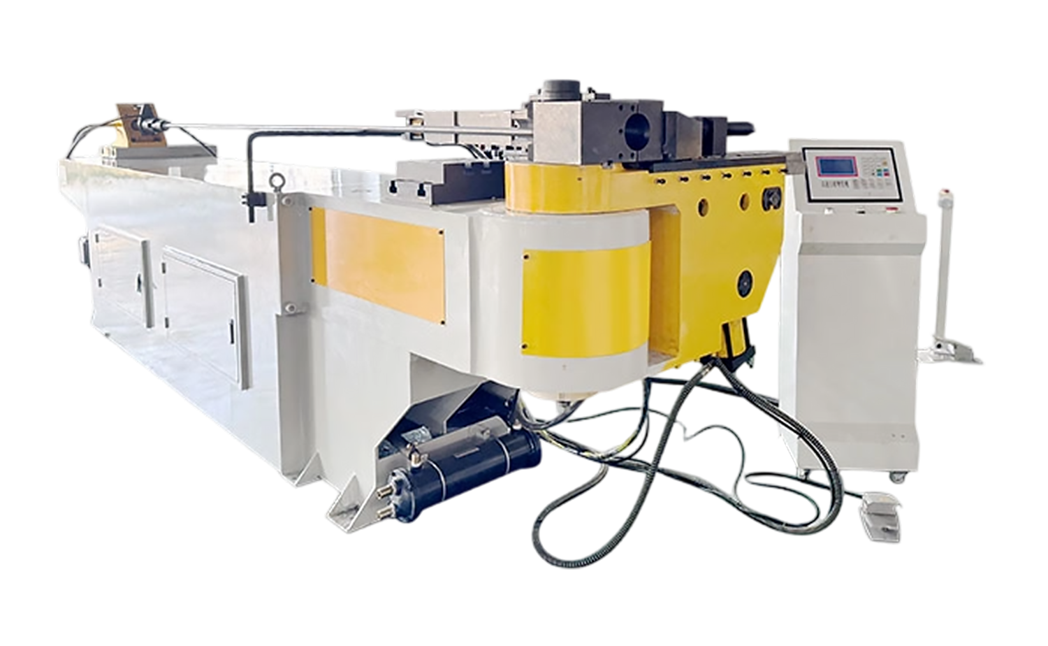
- NC S Series Mandrel Hydraulic Tube Bender with Easy-Program Setting
- CNC M Series Fully Automatic Multi-Radius Tube Bending Machine
- NC M Series Hydraulic Tube Bending Machine with Mandrel Control
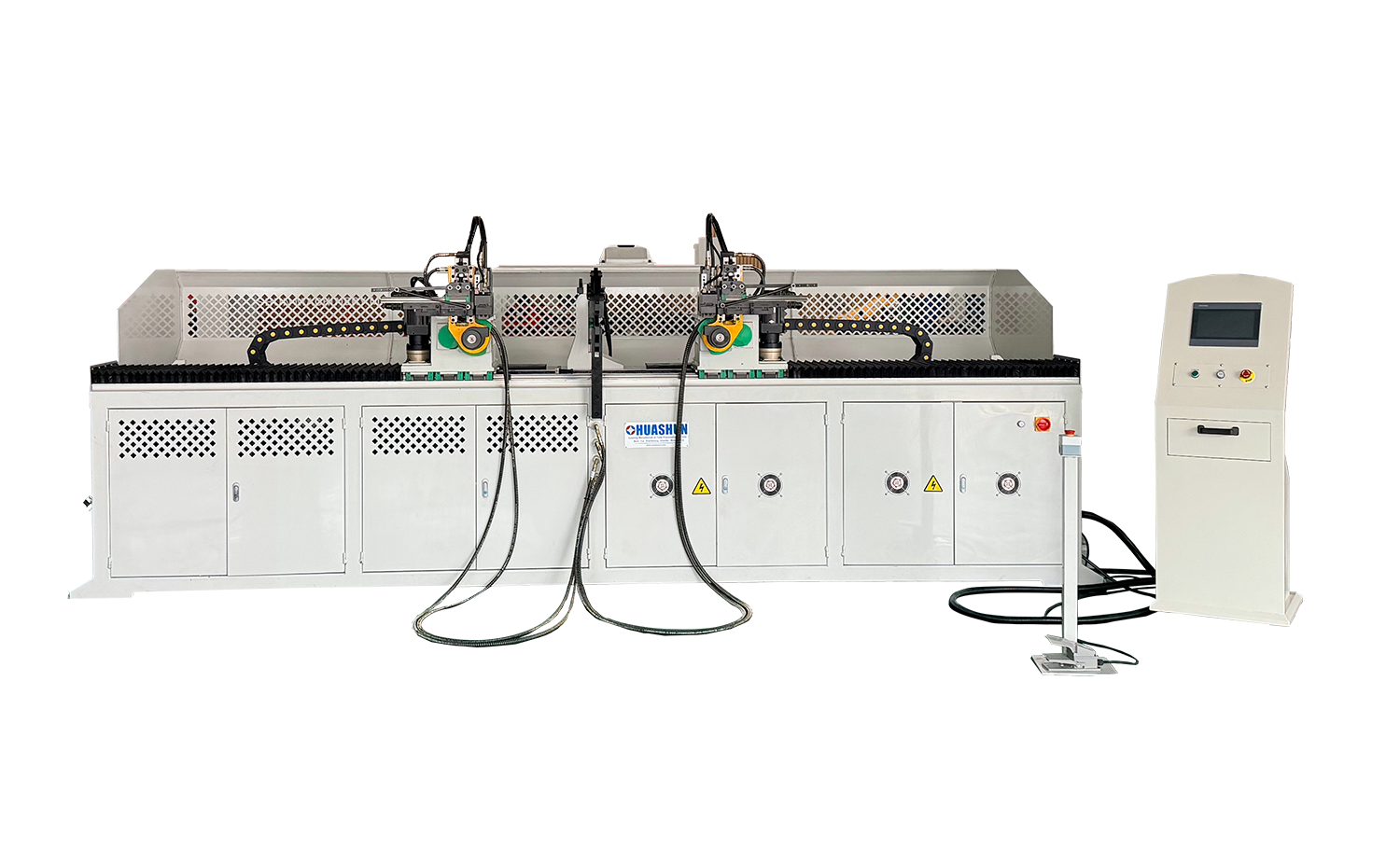
- DB CNC Double Head Tube Bending Machine
- Double Head Automatic Pipe Threading Machine
- ES550 Semi-Automatic Aluminum Cutting Machine for Big Profiles and Tubes
How Do You Calculate Bend Radius Using Formulas, Material Limits, and Tooling Rules?
Date:Sep 04, 2026
Content
A bend radius that works is one that fits three constraints at once: the material's minimum bend radius, the tooling's available radius, and the assembly's dimensional requirement. The shop floor problem usually appears when only one of those constraints is considered. For example, a 40 mm OD aluminum tube with a 2 mm wall may need a 5D radius to avoid wrinkles. If an engineer specifies 2D without checking the alloy temper, the production run can fail.
The key point is that calculating bend radius is a design decision, not a post-process check. It has to happen before the tooling is ordered or the tube is cut.
What Bend Radius Really Means
The reference point you use changes the answer. In tube and pipe bending, the centerline radius (CLR) is the standard reference. It is measured from the center of the bend to the center axis of the tube. The inside radius is the CLR minus half the tube OD, and the outside radius is the CLR plus half the tube OD. For sheet metal, the inside bend radius is what designers and die makers usually discuss, because it represents the inner surface of the formed flange.
The distinction matters because the outer wall stretches and the inner wall compresses during the bend. As the radius gets smaller, the outer wall stretch increases. Once stretch exceeds the material's elongation limit, the outside wall fractures or becomes visibly thin. That is the physical limit that drives minimum bend radius calculations.
The Core Formula for Calculating Bend Radius
The first number you need is the minimum bend radius. For sheet metal, the simplest estimation is to multiply the material thickness by a factor that depends on the material's ductility.
Bend allowance is then used to estimate the flat length of the part. One common formula for a 90-degree bend in mild steel is:
Bend Allowance (BA) = [(0.017453 × Inside Radius) + (0.0078 × Material Thickness)] × Bend Angle
This formula gives a close approximation for many air-bending setups. For tubes, the bend allowance along the centerline is simply the arc length of the centerline, often computed as:
BA = (π × CLR × Bend Angle) / 180
These formulas give you a starting point. They do not tell you whether a given radius is manufacturable without springback, wall thinning, or ovality.
Typical minimum bend radius factors
| Material | Sheet metal factor (x thickness) | Tube factor (x OD) |
|---|---|---|
| Mild steel | 1.0 to 1.5 | 1.5 to 2.0 |
| Stainless steel | 2.0 to 3.0 | 2.0 to 3.0 |
| Aluminum (6061-T6) | 2.0 to 4.0 | 2.5 to 5.0 |
| Copper | 1.0 to 2.0 | 1.0 to 1.5 |
These factors are not substitutes for material certification or tooling data. They are starting points for a feasibility check.
The Real Constraints: Material, Wall Thickness, and Tooling
A smaller radius is not automatically achievable with the same tooling. When a tube is bent to a tight radius, three things happen: the outer wall thins, the cross-section becomes oval, and springback pushes the final angle away from the set angle. Each of these effects has a measurable tolerance.
- Wall thinning: For a 1D bend in carbon steel, thinning can exceed 20% of the nominal wall. For hydraulic and pressure lines, this is often unacceptable.
- Ovality: A bend that is not supported by a mandrel can flatten by 10% or more. Many industry codes cap ovality at 8% for pressure service and 5% for critical lines.
- Springback: High-strength alloys and stainless steel can spring back several degrees. The final radius after springback is always slightly larger than the tool radius.
This is why a proper calculation includes tooling and process settings, not just a geometry formula. A rotary draw bender with a mandrel can go tighter than a compression bender. A CNC machine with multiple axes can control the feed and bend speed to reduce thinning.
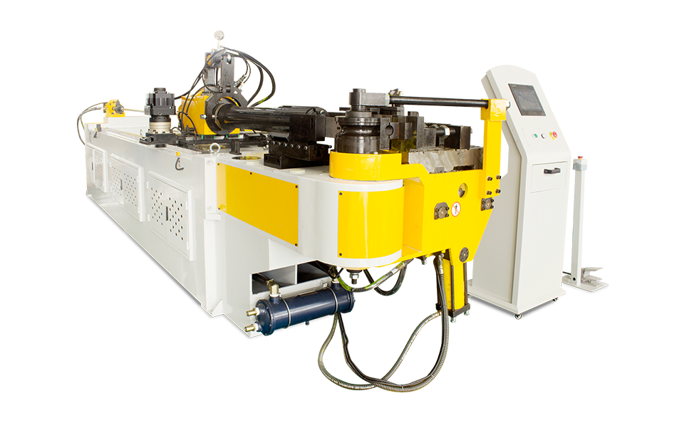 CNC M Series Fully Automatic Multi-Radius Tube Bending MachineThis fully automatic bender offers three programmable servo axes for precise feeding and rotation, supporting multiple bend modes. Its mandrel lubrication and centralized greasing systems enhance reliability for complex radius calculations and material thinning concerns.View Product →
Worked Example: How to Apply the Calculation
A reliable way to apply the calculation is to check the radius-to-OD ratio before you think about bend allowance. Imagine you need to bend a 2-inch schedule 40 steel pipe. The actual OD is 2.375 inches and the wall is 0.154 inches. If the customer wants a 90-degree bend with a 6-inch centerline radius, first check the radius-to-OD ratio.
- Calculate the ratio: 6 ÷ 2.375 = 2.53. This is a 2.5D bend.
- For mild steel, 2.5D is usually safe with a mandrel. Without a mandrel, expect more ovality and a flattened inner wall.
- Calculate the centerline arc length: (π × 6 × 90) / 180 = 9.42 inches.
- Check springback: If the material is Grade B carbon steel, springback may be around 1 to 2 degrees. Set the machine to 88 to 89 degrees for a 90-degree part.
A semi-automatic hydraulic bender with a mandrel can handle this type of steel pipe job consistently, especially when the production run is small to medium.
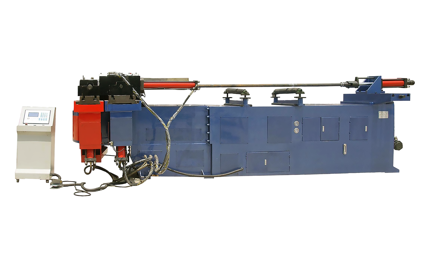 NC L Series High-Performance Hydraulic Pipe Bending MachineA semi-automatic hydraulic bender with clockwise bending and hydraulic clamping, ideal for medium runs. It stores 16 programs with spring-back compensation and handles steel, stainless, aluminum, and more, providing consistent results for radius-to-OD checks.View Product →
This same flow works for aluminum, stainless, and copper, but the factors change. For aluminum, the radius may need to increase to 3D or 4D unless the temper is soft and a mandrel is used.
Practical Rules for Design and Tooling
When you are working on a new product, follow these rules before you quote a job.
- Always use wall thickness, not nominal OD, when evaluating thinning.
- For tubes, confirm if the radius is a centerline radius or an inside radius. Do not assume the drawing uses the same reference as the tooling.
- For sheet metal, an inside radius smaller than the material thickness requires a sharp die with special operators and can still crack.
- When multiple radii are on one tube, keep the tightest radius as the starting point. All other bends should be equal to or larger than that.
- If a tight radius is unavoidable, plan for a mandrel or a higher alloy with greater elongation.
For production jobs in areas like HVAC system piping or automotive manufacturing, the radius choice affects the bend tooling setup, the wall thinning allowance, and the final leak-test pass rate.
When to Consult the Machine Manufacturer
You can calculate a radius on paper, but the manufacturable answer depends on the bender you run. A machine with a larger centerline radius tooling set can produce consistent bends for hydraulic lines. A fully automatic CNC machine with servo-hydraulic controls can compensate for springback across a batch. These are the questions that need a machine manufacturer's input.
Provide the tube OD, wall thickness, material specification, and the desired centerline radius. With those four values, the bender manufacturer can recommend a die set, mandrel type, and bend speed. It is a much shorter path than scrapping a tooling order.
For high-mix production, a fully automatic machine with servo-hydraulic control gives you repeatable bend angles and the ability to run multiple jobs without manually resetting stops. For single-purpose jobs, a semi-automatic hydraulic bender can do the work at a lower capital cost.
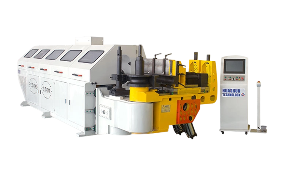 CNC L Series Fully Automatic Tube Bending Machine with Servo-Hydraulic ControlThis fully automatic machine combines servo-hydraulic control with three programmable axes, enabling repeatable angles for high-mix production. It includes mandrel lubrication and a touchscreen PLC for easy monitoring, suitable for jobs requiring precise radius adjustments.View Product →
The Bottom Line
Calculating bend radius is a straightforward task when you have the right inputs. Find the maximum allowable outer wall stretch, set the radius above the minimum for the material, and choose a bender with tooling that can hold the radius and control springback. If you are not sure about the tube or the tooling, send the material spec and the desired radius to the machine supplier before committing to a die set.
Recommended Articles



Copyright © 2025 Huashun Technology All Rights Reserved.
Custom Precision Tube Forming Machine Manufacturers