
 English
 русский
 Español
- NC M Series Hydraulic Tube Bending Machine with Mandrel Control
- NC S Series Mandrel Hydraulic Tube Bender with Easy-Program Setting
- DEF50PVS Servo Tube Chamfering Machine for Short Metal and PVC Tubes
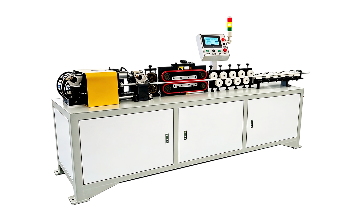
- SC-30 Chipless Tube Straightening and Cutting Machine
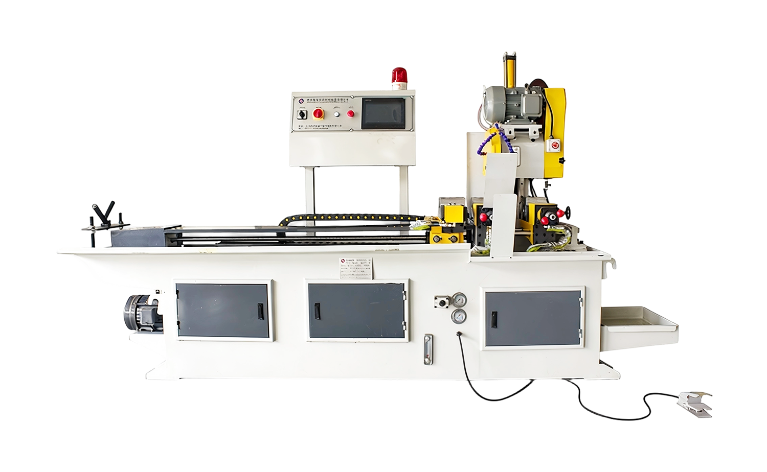
- CNC Series Fully Automatic Servo Feeding Tube Cutting Machine
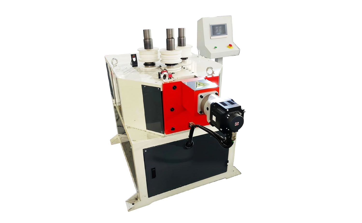
- CNC Series Tube Roll Bending Machine for Metal Profiles
Mandrel Bent Tube: How the Process Works, When It's Required, and Machine Setup
Date:Sep 11, 2026
Content
If a bend on your drawing calls for a radius tighter than about twice the tube's outside diameter, or the wall is thin relative to the diameter, an unsupported bend will almost always fail inspection. The cross section goes oval, the outer wall thins past its minimum, and wrinkles form along the inside of the radius. A mandrel bent tube solves this at the source: a polished support element is inserted into the bore and held at the point where the tube starts to curve, so the metal forms over solid steel instead of collapsing into empty space. The result is a rounder cross section, controlled wall thinning, and a smooth inside radius—the characteristics that exhaust, hydraulic, aerospace, and heat-transfer parts are specified around. This article explains how the process works, the two ratios that tell you when it is genuinely required, how to choose between mandrel types, and what a bending machine must control to produce repeatable results.
What Happens Inside a Mandrel Bent Tube
A mandrel bent tube is produced by rotary draw bending, the standard process for precision tube work. The clamp die grips the tube against the bend die, the pressure die pushes the straight portion forward, and the bend die rotates to draw the tube around the selected centerline radius. Inside the bore, the mandrel shank is fixed to an actuator on the machine, and its nose sits just past the line of tangency—the exact point where the straight tube begins to curve. At that spot the material is stretched on the outside of the bend and compressed on the inside at the same time, and it has no rigidity of its own until the new shape has fully formed around the die.
Without internal support, three defects appear, usually together. Ovality flattens the cross section, which can interfere with fittings and restrict flow. Wall thinning weakens the outside of the bend, which matters in pressure applications. Wrinkles build along the inside radius, creating turbulence and stress concentrations. Typical drawing callouts reflect these risks: ovality is often limited to 5–10% of the outside diameter, and wall thinning is commonly capped at 10–25% of nominal wall, with aerospace and high-pressure hydraulic work sitting at the strict end of those ranges. A mandrel working together with a wiper die is how fabricators hold those numbers on tight radii; on open bends with heavy walls, plain rotary draw bending can still pass inspection without any internal support.
When a Mandrel Bent Tube Is Actually Required
The Two Ratios That Decide It
Two dimensionless values predict whether a bend needs internal support long before any metal is cut. The first is the D of bend: the centerline radius divided by the tube's outside diameter. A 2D bend is far more aggressive than a 4D bend and strains the wall much harder. The second is the wall factor: outside diameter divided by wall thickness. A higher wall factor means thinner, more collapsible tube. Read together, they tell you which tooling package the job needs before the first setup sheet is written.
| Wall factor (OD / wall thickness) | Typical bend radius | Internal support required |
|---|---|---|
| Below 10 | 1.5D–3D | Usually none; heavy wall resists collapse on its own |
| 10–25 | 1.5D–2D | Bullet or plug mandrel on the tighter radii |
| 25–40 | 1.5D–2.5D | Bullet or ball mandrel plus wiper die |
| Above 40 | Any radius | Full ball mandrel set, wiper die, and disciplined lubrication |
Applications Where Mandrel Support Is Standard
Certain product families are specified around mandrel quality from the start. Automotive exhaust systems and headers use tight, compound bends where a smooth inside radius keeps exhaust gas moving; wrinkles act as restriction and turbulence. Hydraulic and fuel lines in thin-wall steel or stainless rely on mandrel bending to preserve both flow area and wall strength. In aerospace work, flatness and thinning limits are strict enough that mandrel support is effectively mandatory. Heat exchangers, boilers, and refrigeration coils bend thin-wall copper and stainless into U-bends and serpentine shapes where an unsupported bend would simply fold. Automotive manufacturing alone combines all of these demands—exhaust, fuel, brake, and coolant lines—which is why mandrel capability is treated as a baseline requirement on bending equipment serving that industry.
Where the Mandrel Can Be Skipped
Handrails, guardrails, roll cages, furniture frames, and architectural tube at 2.5D or open radii with moderate walls generally pass inspection without internal support. For one-off bends, sand filling or frozen-media techniques can substitute in a pinch, though both are slow and messy. Adding a mandrel where the part does not need one costs setup time, lubricant, tool wear, and operator attention for no measurable quality gain—on high-mix work, that overhead adds up quickly.
Bullet Mandrels, Ball Mandrels, and the Wiper Die
Mandrels are not one-size-fits-all, and choosing the wrong type shows up immediately as flats or galling in the bend. A bullet mandrel, sometimes called a plug mandrel, is a single fixed nose on the end of the shank. It is simple, inexpensive, and adequate when the wall factor is moderate and multiple bends are spaced far enough apart that the tube does not need support past the tangent line. A ball mandrel adds one to three hinged ball segments behind the nose, so support extends beyond the tangent as the bend forms. That articulation is what makes thin-wall tube, 1.5D to 2D bends, and closely spaced or compound bends possible at all.
The mandrel rarely works alone. The wiper die—a hardened blade seated in the pocket behind the bend die on the inside radius—peels each new wrinkle flat before it can set. Both tools run against the tube bore under high pressure, so lubrication is not optional; a dry or undersized mandrel will gall the bore and drag the wall. Mandrel material matters too: aluminum bronze noses resist galling on stainless tube, while hardened tool steel is the standard choice for carbon steel and aluminum work.
| Tool | Construction | Typical application |
|---|---|---|
| Bullet / plug mandrel | Single fixed nose on the shank | Moderate wall factors; bends at 2D or larger with generous spacing |
| Ball mandrel (1–3 balls) | Nose plus hinged ball segments | Thin-wall tube, 1.5D–2D bends, compound or closely spaced bends |
| Wiper die | Hardened blade trailing the inside radius | Wrinkle prevention on tight bends; used together with the mandrel |
What the Bending Machine Must Control
A mandrel bent tube is only as repeatable as the machine's mandrel handling, and this is where general-purpose benders fall short. The mandrel must advance before the bend starts and retract cleanly afterward, with timing linked to the bend arm position. Too early, and the nose is dragged through the forming zone and scarred; too late, and the first degrees of the bend form unsupported, which is exactly where most collapse begins. Machines with no mandrel actuator at all simply cannot make these parts.
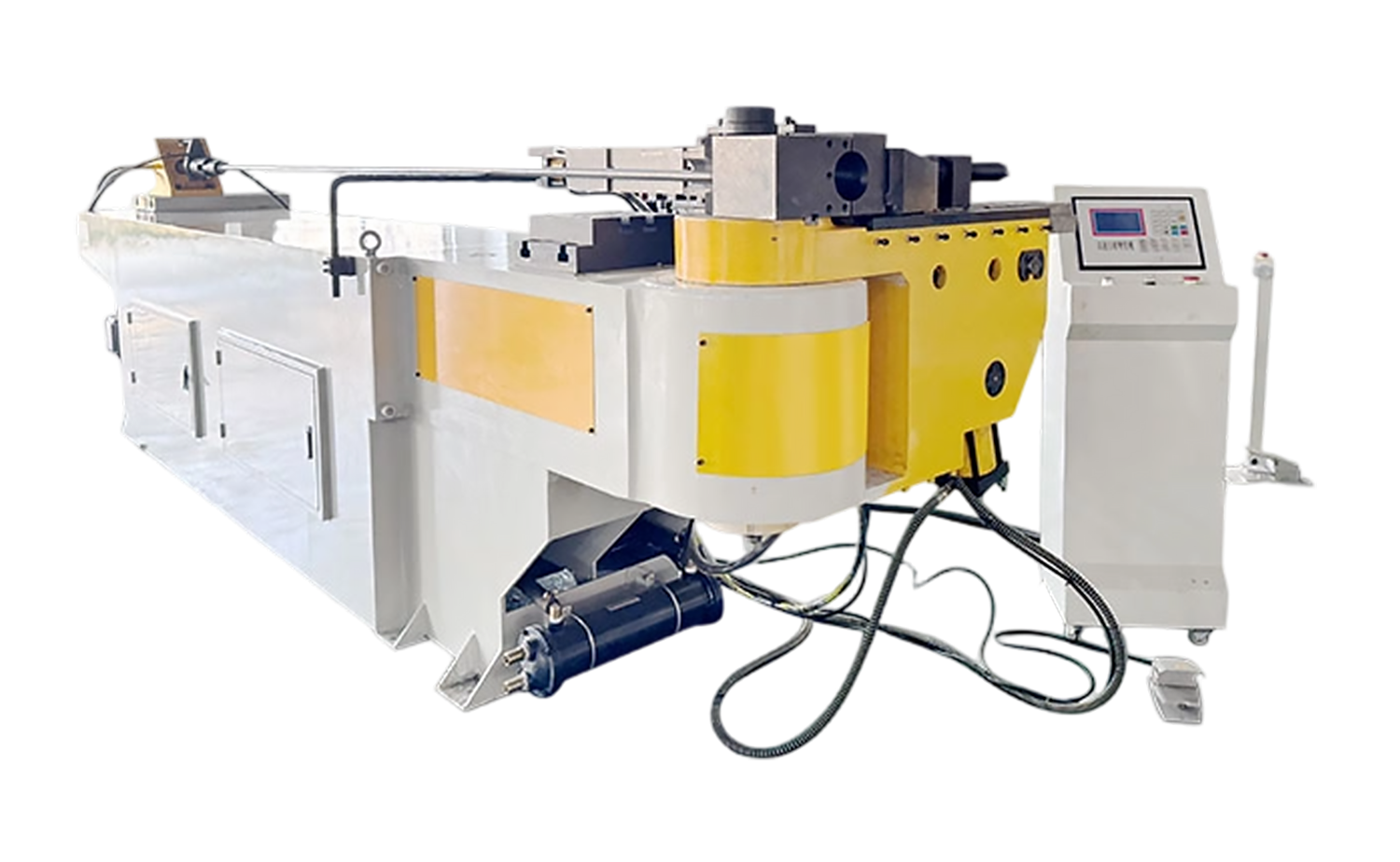 NC M Series Hydraulic Tube Bending Machine with Mandrel ControlAn NC semi-automatic bender with programmable spring-back compensation, hydraulic clamping on both dies, and adjustable pressure-die speed, suited to mandrel bending jobs where clamp support and smooth hydraulic control matter.View Product →
Rigidity around the bend head matters as much as the controller. Thin-wall work needs adequate clamp die length so the tube never slips, pressure-die assist to push material into the bend and reduce thinning, and smooth hydraulic control so the mandrel does not jerk under load. When any of these elements is weak, the symptoms—flats, galling marks, inconsistent thinning—appear across a batch even though the program has not changed. Before quoting a mandrel job, confirm that the machine covers four points:
- Programmable mandrel advance and retract timing tied to bend arm angle
- Clamp length and clamping force matched to the wall thickness
- Pressure-die assist or boost to feed material and limit outer-wall thinning
- A rigid bend head with smooth hydraulic motion to protect the mandrel surface
Matching Equipment to Batch Size and Industry
Batch size and part mix should drive the automation level, not the other way around. For job shops and contract manufacturers handling short runs and frequent changeovers, an NC semi-automatic mandrel bender with straightforward program setting keeps changeover time low while still locking in the two things that cannot be left to operator feel: bend angle and mandrel timing.
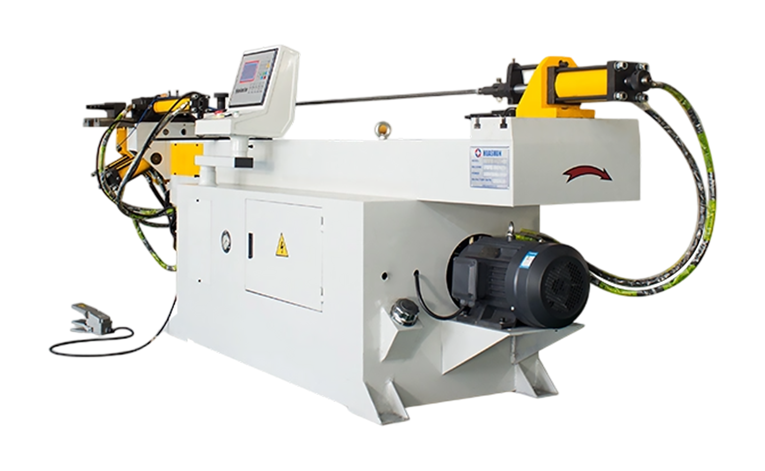 NC S Series Mandrel Hydraulic Tube Bender with Easy-Program SettingStores up to 16 programs of 16 bends each with per-angle spring-back settings, letting job shops lock in bend angle and mandrel timing while keeping changeover quick for short runs and frequent part changeovers.View Product →
Once volumes climb and the same family of parts runs every week, CNC capability pays for itself. Multi-radius CNC machines store complete bend programs—including mandrel timing, clamp and pressure die positions, and multiple radii on a single tube—so a trained setter reproduces part number one on part number five hundred without re-tuning. That repeatability is exactly what exhaust, HVAC coil, and hydraulic fitting suppliers audit when they qualify a bending cell.
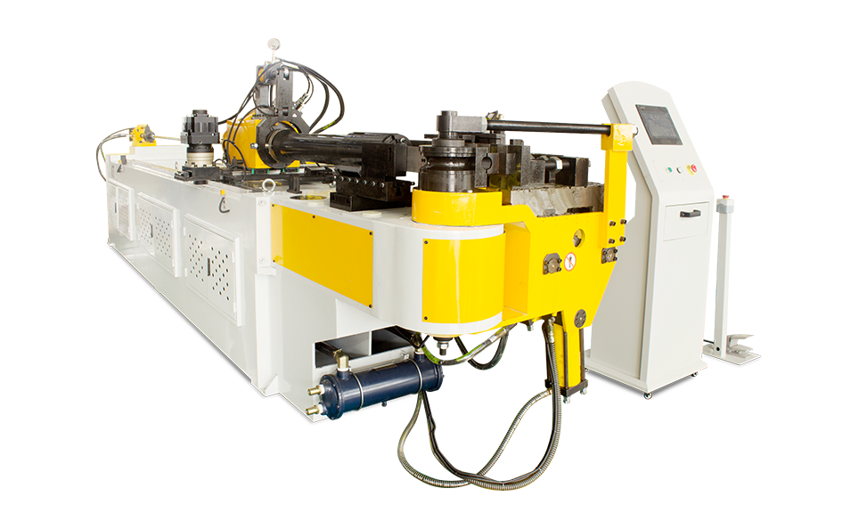 CNC M Series Fully Automatic Multi-Radius Tube Bending MachineA fully automatic CNC bender with servo-driven feeding and rotation, pressure-die assist, and mandrel lubrication, delivering the stored multi-radius programs and repeatability required for exhaust, HVAC coil, and hydraulic fitting production.View Product →
Industry requirements shape the configuration as much as volume does. Aerospace and automotive suppliers document ovality and thinning bend by bend; coil producers prioritize serpentine consistency across thousands of cycles. Whichever applies, the specification on the drawing should map directly to a machine capability: if the drawing calls for 1.5D on 0.9 mm wall, the quoted machine must show a ball mandrel package, wiper die support, and mandrel timing control—anything less is a mismatch that surfaces during first article inspection.
The mandrel itself is a simple piece of polished steel, but a mandrel bent tube is the output of a tuned system: the right mandrel type for the wall factor, a wiper die matched to the radius, correct lubrication, and a machine that controls timing precisely. Get those four elements aligned and tight-radius bends stop being a source of scrap and rework; leave any one of them out and the defects—ovality, thinning, wrinkles—return no matter how skilled the operator is. For a closer look at how precision pipe bending equipment is engineered around these requirements, our industry overview of pipe bending precision covers the machine-side details in depth.




Copyright © 2025 Huashun Technology All Rights Reserved.
Custom Precision Tube Forming Machine Manufacturers