
 English
 русский
 Español
- DEF50PVS Servo Tube Chamfering Machine for Short Metal and PVC Tubes
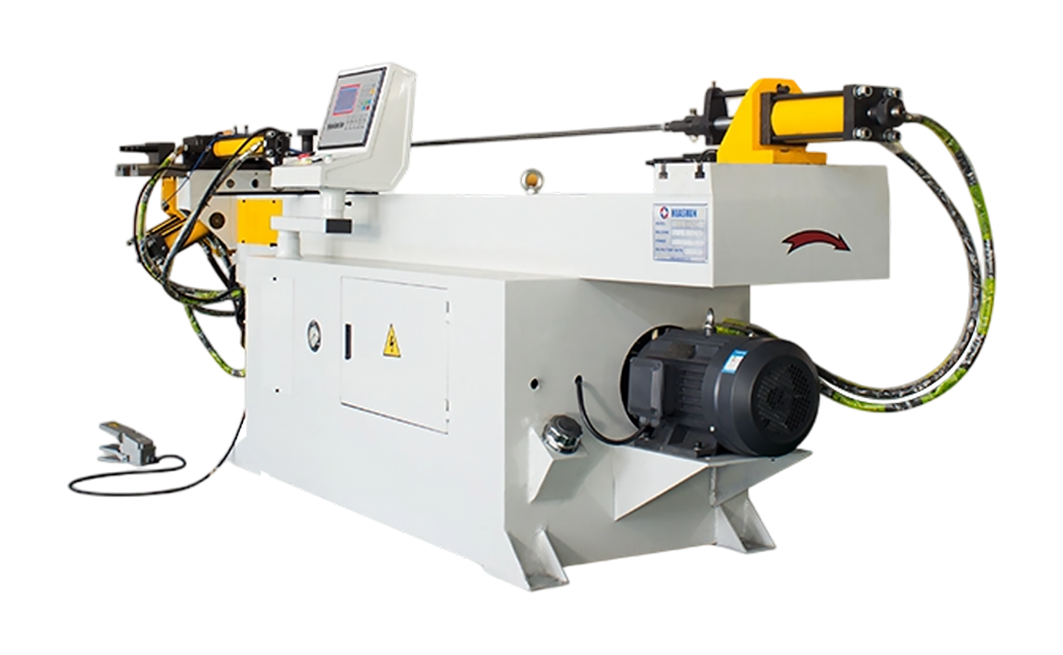
- NC S Series Mandrel Hydraulic Tube Bender with Easy-Program Setting
- DEF680CNC Series Fast Speed Servo Double Head Tube Chamfering Machine
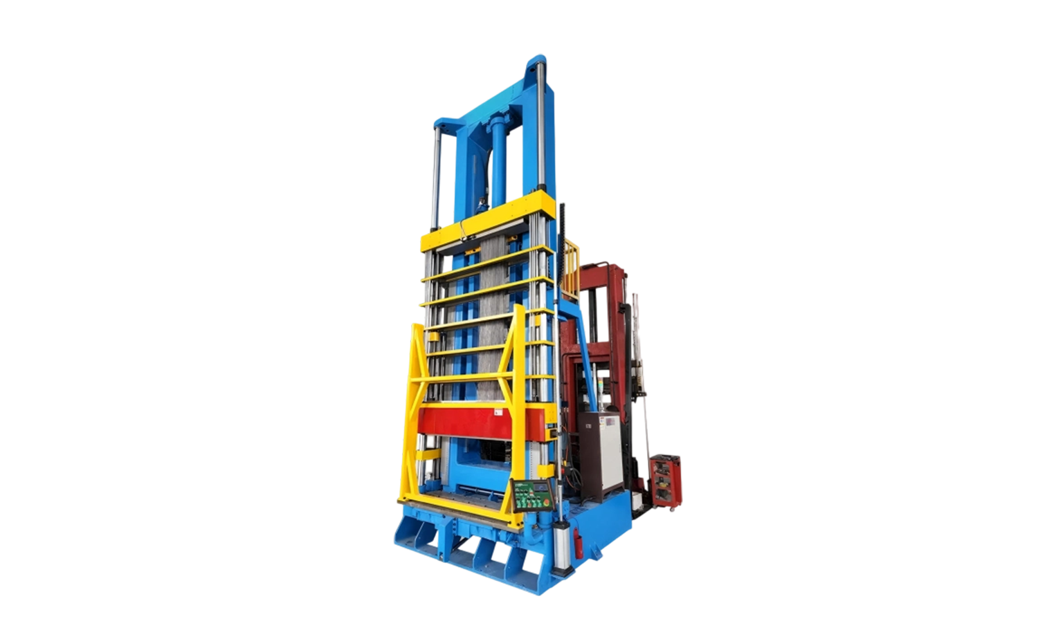
- Quick Changeover Vertical Tube Expanding Machine
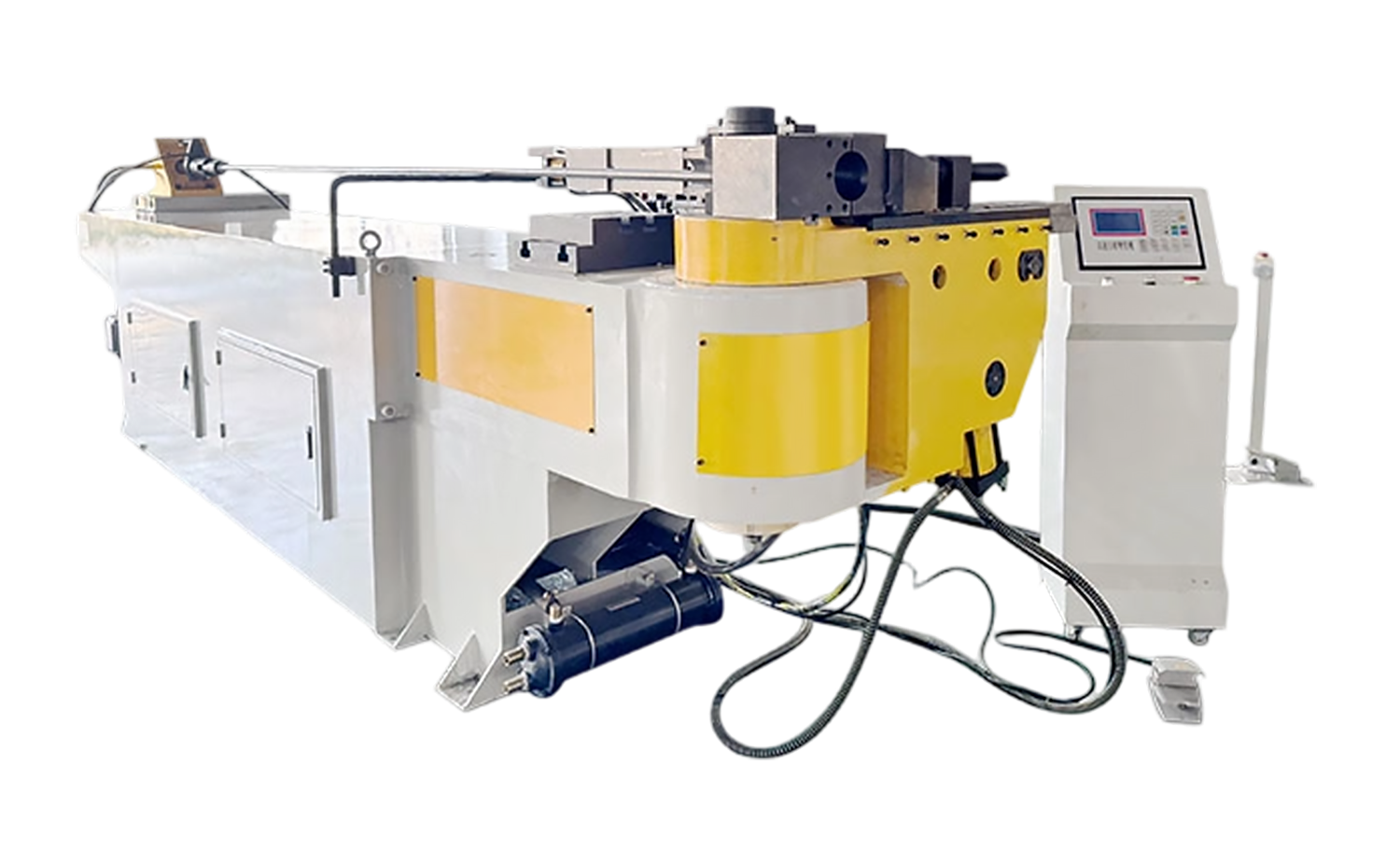
- NC M Series Hydraulic Tube Bending Machine with Mandrel Control
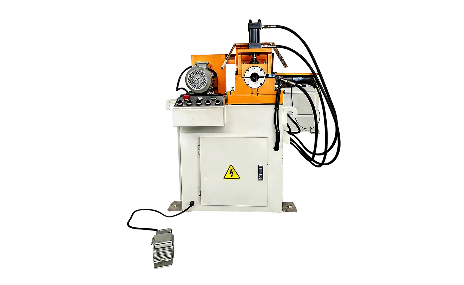
- EF PV1 Series Hydraulic Semi-Automatic Tube Chamfering Machine
Chamfering Meaning: Definition, Process, Benefits, and Tube Applications
Date:Nov 19, 2026
Content
- 1 What Does Chamfering Mean in Manufacturing?
- 2 Chamfer vs. Bevel vs. Fillet: Clearing Up the Terms
- 3 Why Chamfering Matters: Function and Benefits
- 4 Common Chamfering Methods and Machines
- 5 How Chamfering Is Specified and Measured
- 6 Chamfering in Tube and Pipe Fabrication
- 7 Choosing the Right Chamfering Approach
- 8 Practical Tips for Better Chamfering Results
- 9 Chamfering Meaning, in One Sentence
If you have seen a callout such as “C1” on a drawing and wondered what it means, you are not alone. Chamfering is one of those shop-floor terms that everyone uses but few people stop to define. In plain language, chamfering is a machining operation that removes a sharp corner or edge and leaves a controlled angled surface. The angle is often 45 degrees, but it can be any angle the part requires. “Chamfer” can describe the cut feature itself, while “chamfering” describes the process of making it.
The purpose is not simply to make a part look finished. A chamfer can protect hands, guide a component into a hole, prepare an edge for welding, or replace an unpredictable burr with a known geometry. In tube and pipe work, the same idea applies to the end of a tube: a small internal or external angle can make assembly cleaner, safer, and more repeatable.
What Does Chamfering Mean in Manufacturing?
In manufacturing, chamfering means cutting away material along an edge or corner to create a flat, inclined surface. The cut is usually defined by a distance and an angle, such as 0.5 mm × 45°, or by a shorthand callout like C1. The “C” stands for chamfer, and the number is normally the leg length in millimeters. A C1 chamfer generally means 1 mm × 45°, although drawing standards and company conventions should always be checked.
Chamfering can be applied to an outside edge, an inside edge, a hole, a shaft, a gear tooth, or a tube end. It may be a finishing step after cutting, or it may be a deliberate design feature that remains for the life of the part. The key point is control: a chamfer has a specified size, angle, and surface condition, while a random scratch or over-polished corner does not.
People sometimes use “chamfering” and “deburring” as if they are the same. They overlap, but they are not identical. Deburring removes the raised burr left by cutting, drilling, or milling. Chamfering creates a defined edge geometry. A chamfer may remove a burr as a side effect, but its main job is to produce a known angled surface.
Chamfer vs. Bevel vs. Fillet: Clearing Up the Terms
These terms are often mixed up because they all describe edge treatment. A chamfer is a flat angled cut, usually with a simple 45-degree geometry. A bevel is also an angled surface, but it is often broader and may be used for weld preparation. A fillet is a rounded transition rather than a flat cut. In everyday shop talk the lines can blur, but the drawing, inspection method, and process should agree.
| Term | Typical shape | How it is described | Common purpose |
|---|---|---|---|
| Chamfer | Flat angled edge, often 45° | C1, 1 × 45°, or length and angle | Remove sharp edges, guide assembly, improve appearance |
| Bevel | Angled face, angle can be shallow | Bevel angle and depth or land | Weld preparation, edge profiling, corner removal |
| Fillet | Rounded inside or outside corner | Radius, such as R2 | Reduce stress concentration, improve strength or flow |
Why Chamfering Matters: Function and Benefits
Chamfering earns its place because it solves practical problems. The most common reasons include:
- Safety and handling. A sharp edge can cut gloves, scratch finished parts, or injure operators during loading and inspection.
- Assembly and alignment. A small lead-in chamfer helps a shaft, fitting, or tube enter a bore without catching.
- Weld preparation. A controlled bevel or chamfer can improve fit-up and help the weld penetrate consistently.
- Burr control. Chamfering replaces a random burr with a defined edge that is easier to inspect and clean.
- Fit and sealing. In hydraulic and pneumatic work, a smooth chamfer can protect seals and O-rings from nicks.
- Appearance and coating. A uniform edge looks better and can help coating or plating cover the corner more evenly.
- Stress and durability. At a transition, a chamfer can reduce the sharp-corner effect that may initiate cracks, although a fillet is often preferred where maximum stress reduction is needed.
None of these benefits happen automatically. A chamfer that is too small may disappear after coating or handling. One that is too large may reduce wall thickness, weaken a tube end, or remove a locating shoulder. The right size depends on the part, the material, and the next operation.
Common Chamfering Methods and Machines
Chamfering can be done with a file, a deburring tool, a grinder, a lathe, a milling machine, or a dedicated chamfering machine. For one-off parts, hand tools are often enough. For production, the choice usually comes down to repeatability, cycle time, and how the part is clamped.
Dedicated machines are common in tube and pipe shops because the workpiece is round, often long, and may need both ends processed. A single-head tube chamfering machine is a practical choice for low to medium volumes or for parts that are easier to load one end at a time. Depending on the tooling and machine configuration, it can chamfer the outside diameter, the inside diameter, or both.
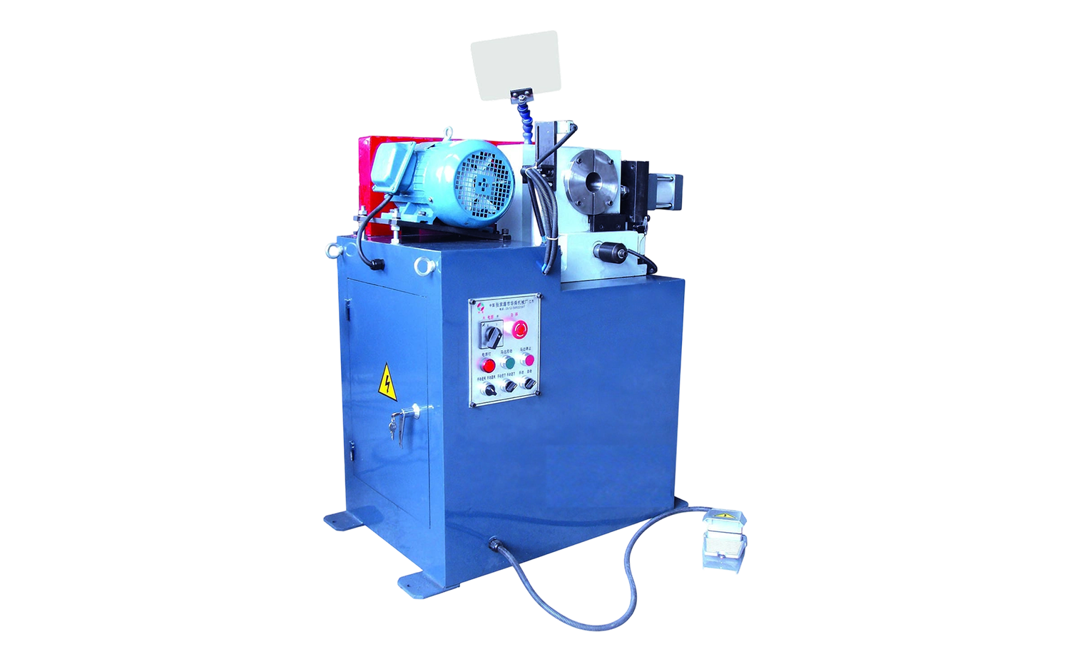 EF AC Series Single-Head Tube Chamfering MachineA practical semi-automatic choice for low-to-medium volumes, with pneumatic chamfering and options for flat, internal, external, or combined cuts.View Product →
Double-head machines process both tube ends at the same time. They suit batches where length consistency and cycle time matter, and they can reduce the handling error that comes from turning a part around. Hydraulic and servo versions differ in setup flexibility, force control, and how consistently they hold the chamfer depth.
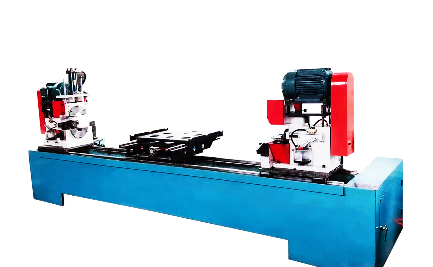 DEF PV Series Double-Head Hydraulic Tube Chamfering MachineProcesses both tube ends at once with hydraulic drive and an automatic feeding rack, suiting batches where length consistency and cycle time matter.View Product →
For tighter tolerances or mixed sizes, servo-driven chamfering machines offer programmable positioning and repeatable depth control. They are not automatically better for every shop; the right choice still depends on tube diameter, wall thickness, material, finish, and the number of changeovers per shift.
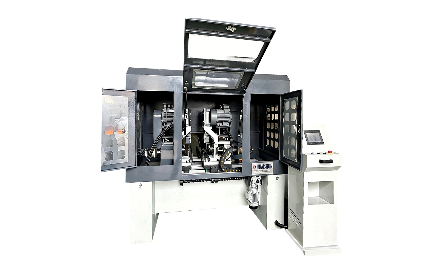 DEF80CNC Series Servo Tube Chamfering MachineServo-controlled knife movement supports programmable positioning and repeatable depth control for tighter tolerances, mixed sizes, and consistent single-pass chamfering.View Product →
If you are comparing machine styles, our tube chamfering machine category groups single-head, double-head, and servo designs in one place.
How Chamfering Is Specified and Measured
A chamfer callout should answer three questions: where, how big, and at what angle. On a drawing, a 45° chamfer is often shown as C1, C2, or C0.5. A non-45° chamfer may be dimensioned with an angle and a length, or with two linear dimensions. For tube ends, the drawing may also specify whether the chamfer is on the OD, the ID, or both, and whether the transition must be concentric.
Inspection usually starts with the basics: angle, chamfer length or depth, and surface condition. A caliper or depth gauge can work for many shop-floor checks, while an optical comparator, profile projector, or vision system is better for small features and edge quality. For high-volume work, go/no-go gauges and first-piece approval help keep the process stable.
Do not ignore the condition of the cut. A chamfer with chatter marks, torn material, or a rolled edge may pass a length check but still cause problems in assembly or welding. The tool, speed, feed, coolant, and clamping all affect the result, especially on stainless steel, aluminum, and thin-wall tube.
Chamfering in Tube and Pipe Fabrication
Tube and pipe work brings its own chamfering questions. A tube end may need an external chamfer to remove the sharp OD edge, an internal chamfer to ease insertion or improve flow, or a weld-prep bevel that is more than a simple edge break. In butt-welded tube assemblies, the end profile can influence fit-up, penetration, and the amount of filler needed.
For hydraulic lines, chamfering can protect seals and O-rings from nicks during assembly. In automotive and HVAC parts, a clean tube end supports consistent joining and helps avoid loose chips or burrs inside the system. In furniture, fitness equipment, and architectural metalwork, the chamfer is often as much about handling and appearance as it is about function.
Material matters. Aluminum can gall or smear if the tool is not sharp and the feed is wrong. Stainless steel may work-harden and needs stable clamping and adequate coolant. Thin-wall tube is less forgiving because too much chamfer depth can reduce the load-bearing section. A machine that is rigid and repeatable is usually more valuable than one that simply claims a high spindle speed.
For a closer look at edge quality in practice, this company news article on chamfering machine precision is a useful read.
Choosing the Right Chamfering Approach
Start with the part, not the machine. The following questions usually narrow the options quickly:
- What is the chamfer specification? Size, angle, OD/ID, and tolerance decide the tooling and inspection method.
- What material and wall thickness? Hardness, toughness, and heat sensitivity affect cutting force, tool life, and the risk of distortion.
- How many parts and how many changeovers? High volume favors dedicated automation; high mix favors quick setup and flexible control.
- How will the part be loaded? Long tubes, short fittings, and heavy pipes need different support and clamping.
- What finish is required? A visible chamfer, a weld-prep bevel, and a burr-free edge are not the same requirement.
It also helps to separate “must have” from “nice to have.” A servo axis may be essential for repeatable depth on a critical part, but unnecessary for a simple deburring step. A double-head machine may pay back quickly in a two-shift operation, while a single-head machine may be the more sensible start for a job shop with varied work.
Practical Tips for Better Chamfering Results
- Set the tool from the part, not from the last job. Confirm the chamfer size and angle before running a new batch.
- Check the first and last piece. Tool wear often shows up at the end of a run, not the beginning.
- Keep chips out of the tube. Internal burrs and chips can cause problems later in assembly or fluid systems.
- Watch tool wear. A dull tool can polish, smear, or tear the edge instead of cutting it cleanly.
- Do not over-chamfer thin-wall tube. Remove only what the specification requires.
- Document the setup. Record tool position, speed, feed, and clamping pressure so the next run is repeatable.
These habits are simple, but they prevent most of the problems that make a chamfer look inconsistent: varying depth, a polished edge on one part and a torn edge on the next, or a burr that reappears after the tool has run for a few hundred pieces.
Chamfering Meaning, in One Sentence
Chamfering means cutting a controlled angled edge to replace a sharp corner with a defined surface. It is a small feature with a large effect on safety, assembly, welding, and finish. Whether you are working with a single tube end or a production run of thousands, the best result comes from matching the chamfer specification to the material, the tooling, and the machine, and then checking the edge, not just the drawing.



Copyright © 2025 Huashun Technology All Rights Reserved.
Custom Precision Tube Forming Machine Manufacturers