
 English
 русский
 Español
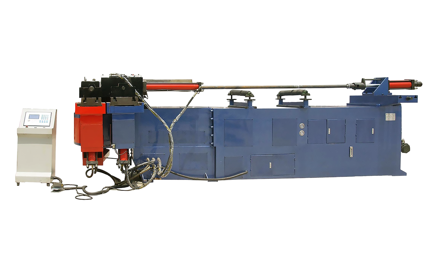
- NC S Series Mandrel Hydraulic Tube Bender with Easy-Program Setting
- NC L Series High-performance Hydraulic Pipe/Tube Bending Machine
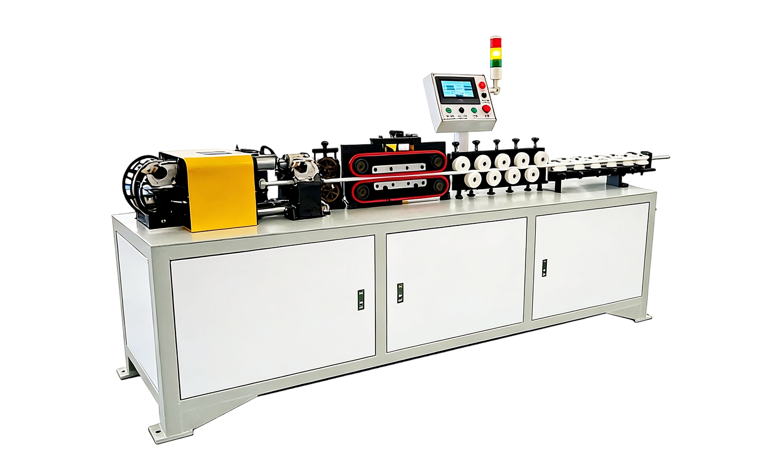
- SC-30 Chipless Tube Straightening and Cutting Machine
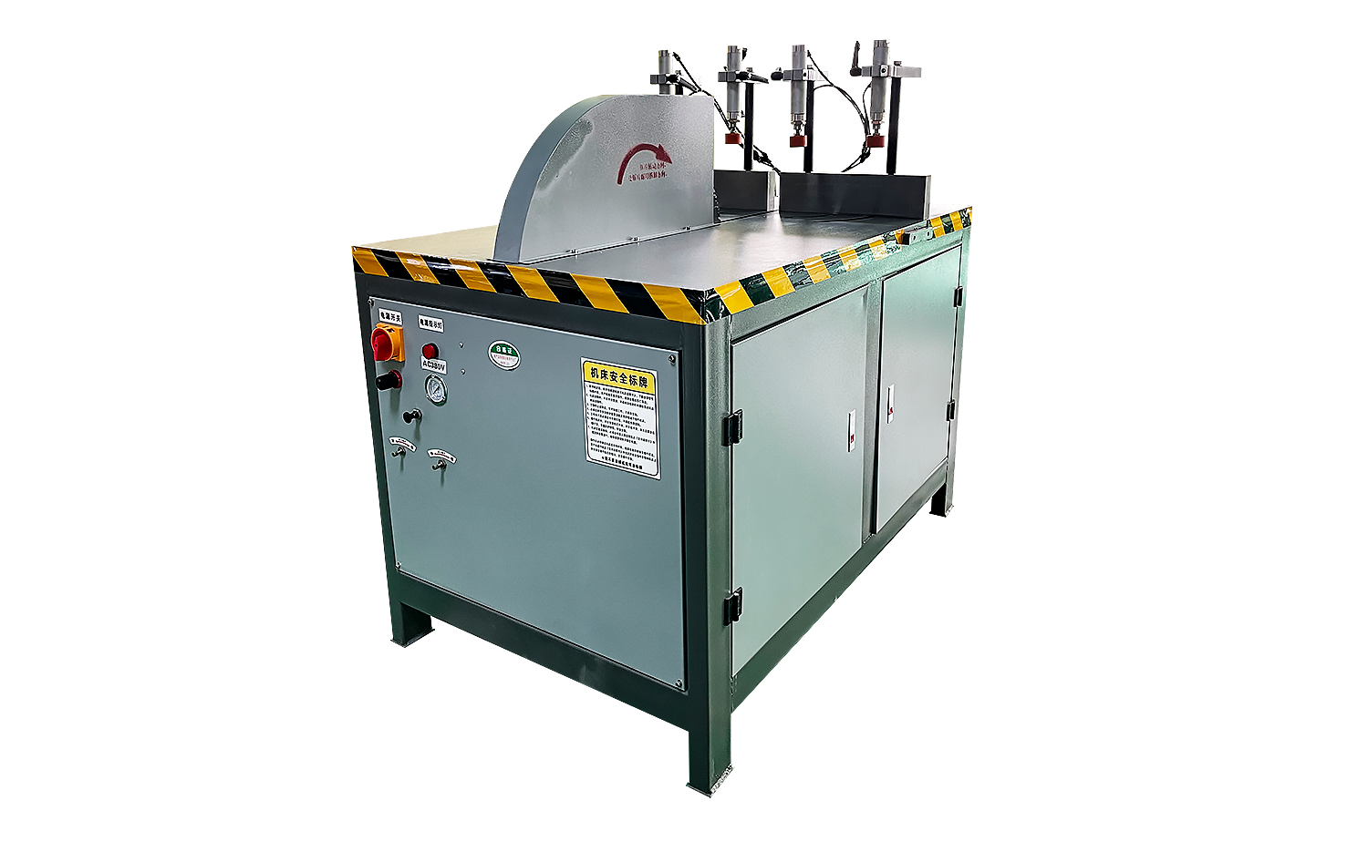
- ES550 Semi-Automatic Aluminum Cutting Machine for Big Profiles and Tubes
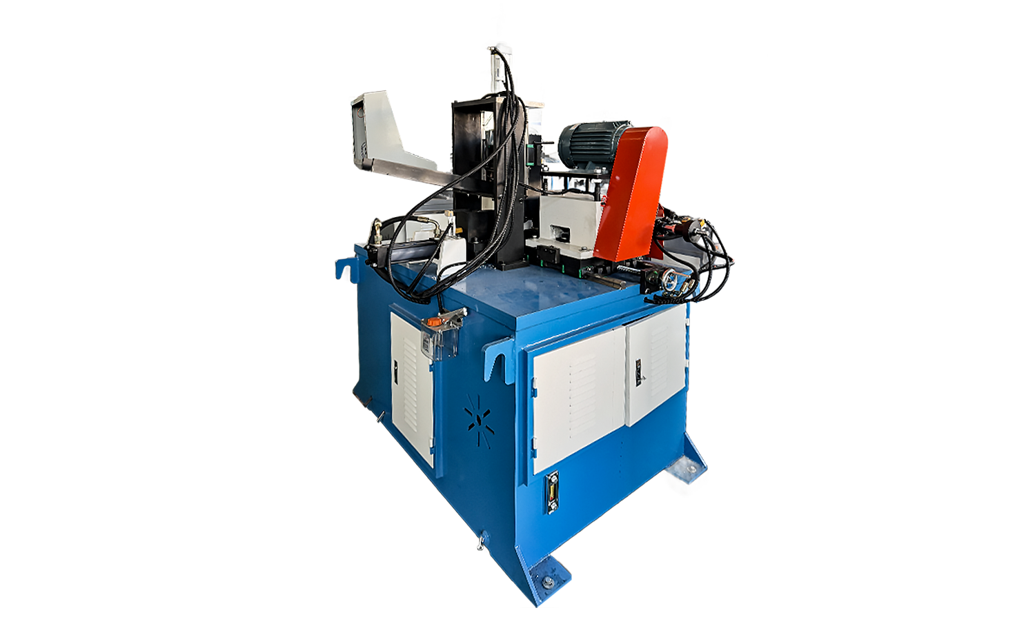
- DEF50PVS Servo Tube Chamfering Machine for Short Metal and PVC Tubes
- Adjustabe Handheld Tube Expanding Machine
Non-Destructive Pipe Testing: Methods, Defects, and Better Tube Fabrication
Date:Nov 14, 2026
Content
- 1 What Non-Destructive Pipe Testing Actually Looks For
- 2 The Core NDT Methods at a Glance
- 3 Matching the Method to the Defect and the Joint
- 4 Where Fabrication Choices Make Inspection Easier
- 5 A Practical Sequence for Tube Shops
- 6 Interpreting Results Without False Confidence
- 7 Bringing NDT Into the Fabrication Conversation
Non-destructive pipe testing is often treated as the last gate in fabrication: the tube is cut, bent, formed, welded, and then inspected. In real shops, that gate is only as reliable as everything that came before it. A test can confirm a sound bend or a clean weld, but it cannot undo a torn wall, a buried crack, or a chamfer that was never square. The practical way to think about NDT is as a conversation between forming and verification—each step tells the next one what to look for.
This guide walks through the main methods, the defects they are good at finding, and the small fabrication choices that make inspection faster and more trustworthy. It is written for tube shop teams who want fewer surprises at the inspection station, not a textbook chapter.
What Non-Destructive Pipe Testing Actually Looks For
NDT does not make a pipe stronger. It reveals discontinuities that are already there, or that may have been introduced by cutting, bending, end forming, welding, or handling. The target list is fairly consistent across industries: wall thinning on the outside radius of a bend, ovality and wrinkling on the inside radius, cracks in the heat-affected zone, lack of fusion, porosity, slag, undercut, seams, laps, and inclusions in the base material.
It helps to separate surface defects from volumetric ones. A surface crack, a lap, or a wrinkle is usually accessible to visual, magnetic particle, penetrant, or eddy current methods. A lack of fusion buried in a weld, or a gradual wall loss inside a bend, needs a volumetric method such as ultrasonic or radiographic testing. Many inspection failures are not caused by a missing technique; they are caused by using a surface method for a volumetric problem, or by inspecting a formed area without accounting for its geometry.
The Core NDT Methods at a Glance
No single method covers every defect, material, and joint configuration. The table below is a practical starting point for pipe and tube fabrication, not a substitute for the applicable code or a qualified procedure.
| Method | Best For | Typical Pipe and Tube Applications | Limits to Keep in Mind |
|---|---|---|---|
| Visual (VT) | Surface discontinuities, weld profile, misalignment, wrinkles | Outside diameter, bend zones, fit-up, final assembly | Access and lighting matter; subsurface defects are invisible |
| Ultrasonic (UT) | Volumetric defects, wall thinning, lack of fusion, cracks | Welds, heavy-wall pipe, bend zones, critical joints | Needs couplant and skilled setup; geometry can complicate scanning |
| Radiographic (RT) | Porosity, inclusions, lack of penetration, volumetric weld defects | Butt welds, critical pipe joints, field girth welds | Radiation safety controls; planar defects may be missed if not oriented |
| Magnetic Particle (MT) | Surface and near-surface cracks in ferromagnetic materials | Carbon steel pipe welds, bends, and heat-affected zones | Only works on ferromagnetic materials; magnetization direction matters |
| Penetrant (PT) | Surface-breaking cracks, porosity, laps | Stainless steel, aluminum, and nonmagnetic weld surfaces | Clean surface required; no subsurface detection |
| Eddy Current (ET) | Surface and near-surface cracks, wall thinning | Heat exchanger tubes, nonmagnetic tubing, production screening | Limited depth; calibration and probe selection are critical |
| Pressure and Leak Testing | Through-wall defects and joint integrity | Completed assemblies, pipelines, pressure-containing parts | Does not size or locate defects; safety controls are essential |
Matching the Method to the Defect and the Joint
For welded pipe, the weld cap and root geometry can hide lack of fusion from radiography if the beam is not aligned with the defect. Ultrasonic testing is often better for planar defects and wall thinning, but it demands a reference standard and a procedure that matches the joint. Magnetic particle testing is a strong choice for carbon steel welds and bend zones, while penetrant testing is often used on stainless steel where magnetic methods do not apply.
Bends deserve their own inspection plan. The outside radius is thinner by nature, and the inside radius can wrinkle if the mandrel, lubrication, or bend speed is wrong. Visual inspection catches wrinkles and surface tearing; ultrasonic testing can map wall loss; magnetic particle testing can find cracks in ferrous bend zones. The key is to inspect the formed area as a formed area, not as straight pipe that happens to be curved.
Edge preparation matters more than many teams expect. A ragged cut or a chamfer that is not concentric can look like a defect on a scan, or it can mask a real one. A clean, repeatable chamfer gives the inspector a stable reference and gives the welder a better chance of a sound joint.
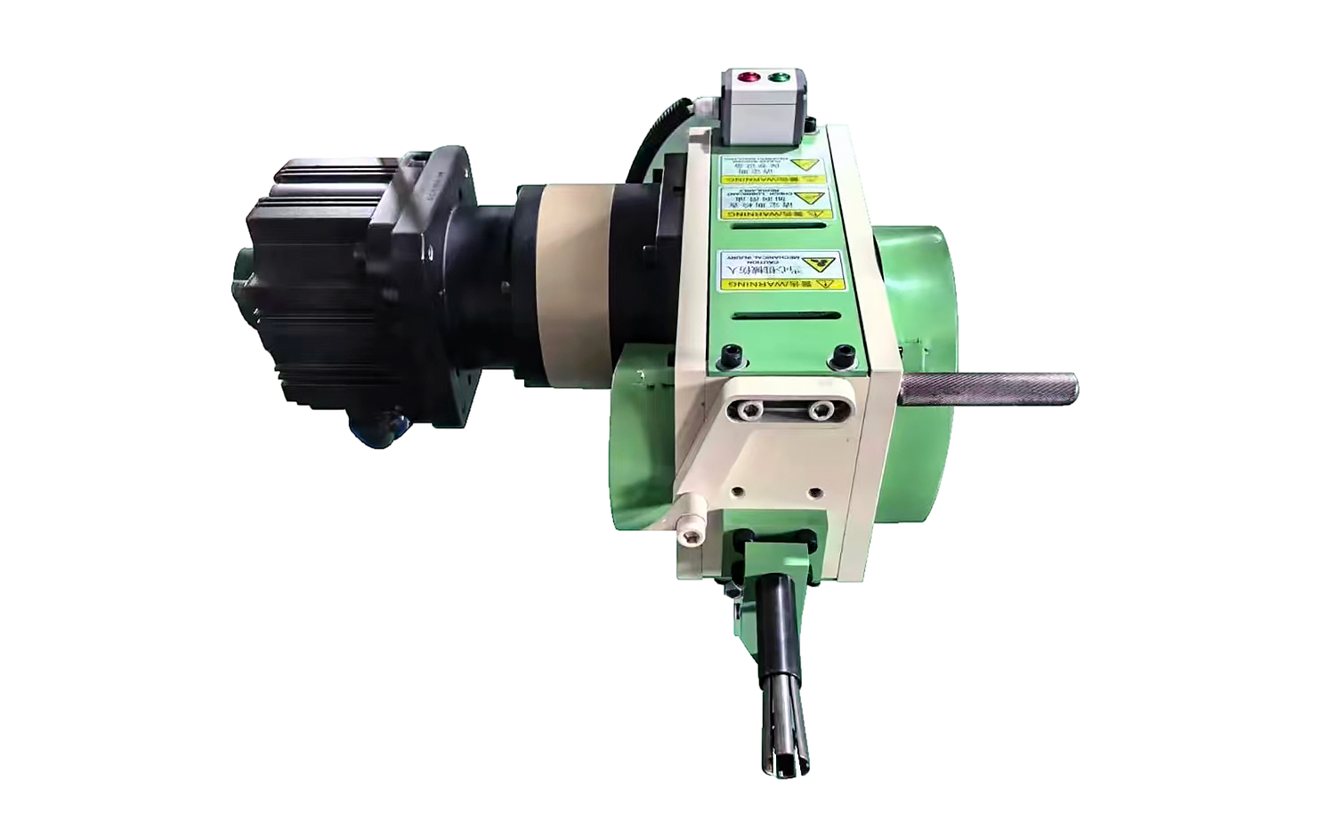
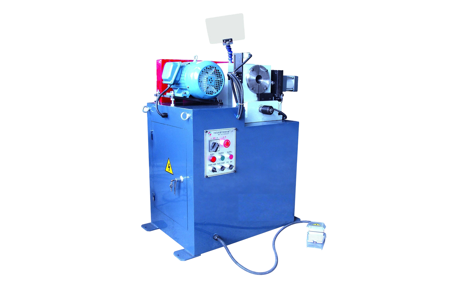 EF AC Series High Precision Tube Chamfering MachineSemi-automatic single-head tube chamfering machine for repeatable flat, internal, and external chamfers on carbon steel, stainless steel, copper, and aluminum.View Product →
Where Fabrication Choices Make Inspection Easier
Inspection starts at the saw. A cut that leaves a heavy burr or a work-hardened edge can fold material into the weld prep, create a false indication, or force the inspector to spend time proving that a mark is not a crack. A square, burr-controlled cut is not a luxury; it is part of the inspection strategy.
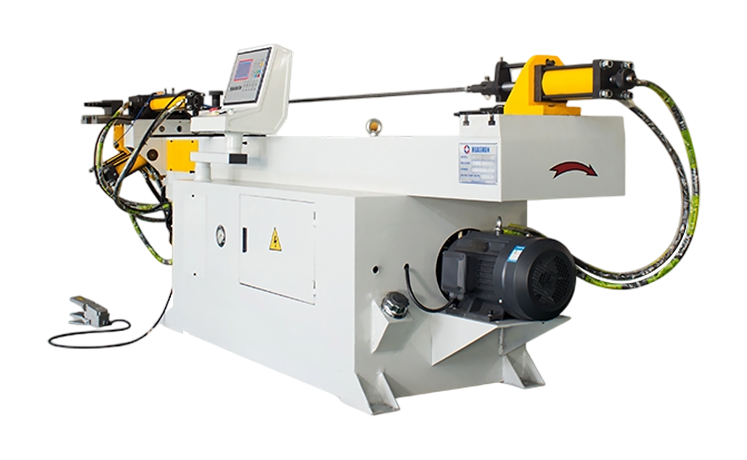
Bending is the next place where NDT outcomes are shaped. Mandrel support, lubrication, bend speed, and tooling condition all affect wall thinning, ovality, and wrinkling. A repeatable CNC bend with documented setup gives the inspector a known geometry to scan and gives the engineer a known baseline for acceptance. For shops that need repeatable multi-radius bends with documented setup, a CNC multi-radius tube bender is often the starting point.
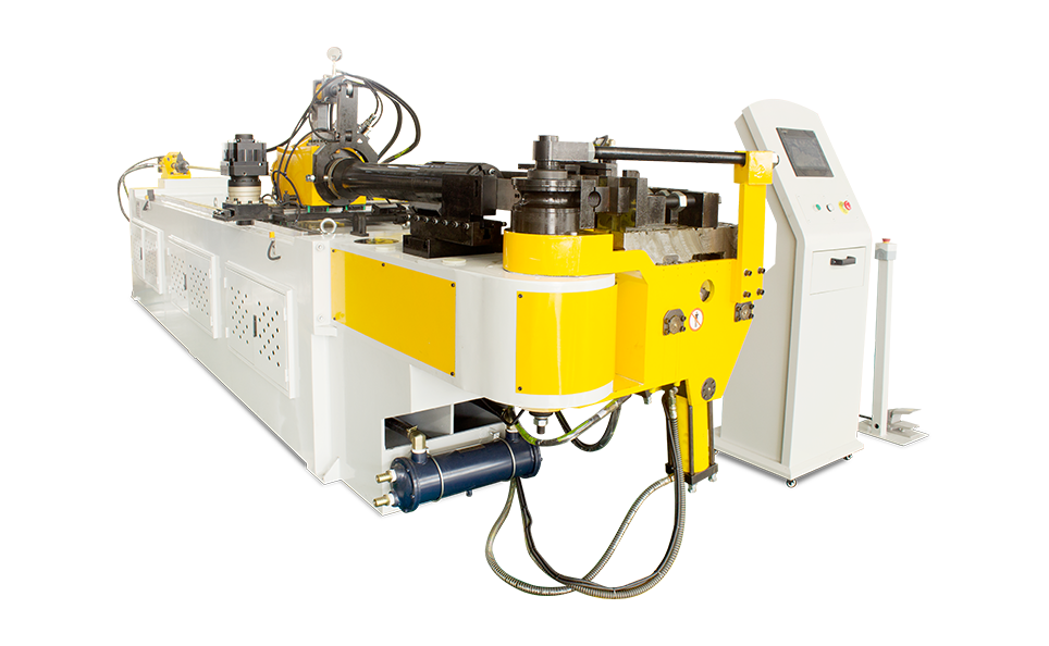 CNC M Series Fully Automatic Multi-Radius Tube Bending MachineFully automatic multi-radius tube bender with programmable servo axes for repeatable bending setups that support consistent inspection baselines.View Product →
End forming and chamfering also leave fingerprints that inspection can read. Excessive thinning, cracking at the formed edge, or an off-center chamfer can turn a simple dimensional check into a full investigation. If you want a deeper comparison of destructive and non-destructive testing methods for metal tube fabrication, our team has put together a practical overview that pairs well with this guide.
The common thread is simple: the more controlled the cut, bend, and edge prep, the less noise the inspector has to sort through. Good fabrication does not replace NDT, but it makes NDT mean more.
A Practical Sequence for Tube Shops
Cutting to length is a good place to start because it sets the reference for every later operation. A fully automatic servo-feeding tube cutting machine can hold length and squareness consistently, which reduces the chance that a downstream chamfer or weld prep will be blamed for a cut problem.
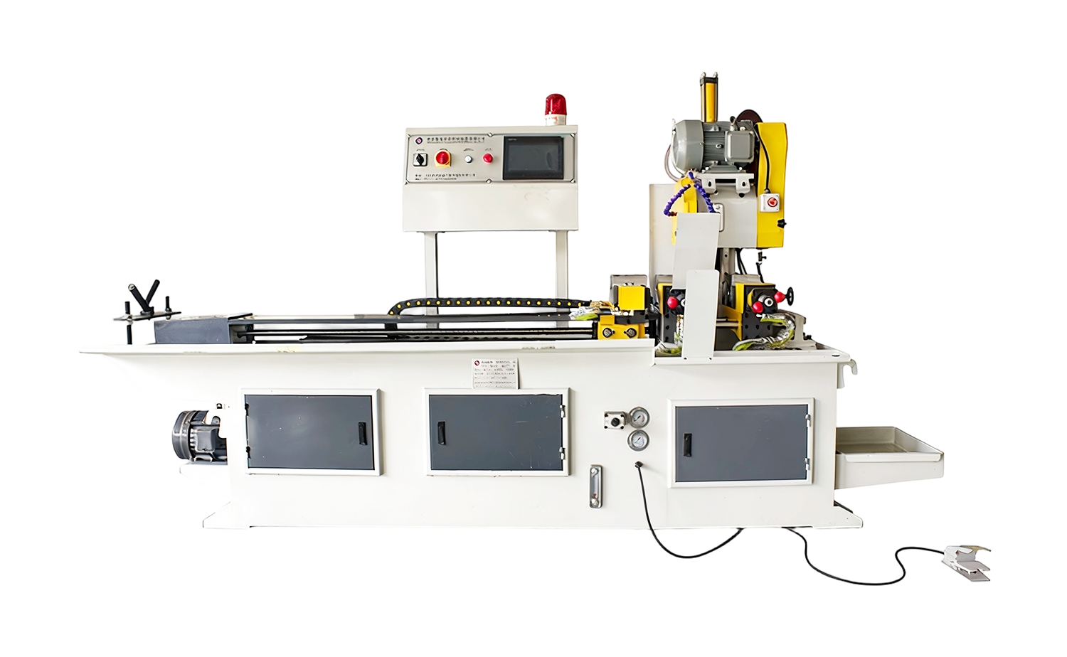 CNC Series Fully Automatic Servo Feeding Tube Cutting MachineFully automatic servo-feeding circular saw for consistent tube length and squareness, with PLC control and burr-free cutting for downstream operations.View Product →
- Verify incoming material: heat number, wall thickness, surface condition, and any mill test reports.
- Cut to length with a process that controls burr, squareness, and heat input.
- Bend or end form with documented tooling and setup parameters, then check wall thinning and ovality.
- Prepare edges and weld surfaces so the joint geometry is stable and repeatable.
- Select the NDT method by material, joint type, defect orientation, and code requirement.
- Record the results, including calibration, operator, procedure, and any rejected indications.
This sequence is not glamorous, but it matches how defects actually appear. It also keeps inspection from becoming a last-minute argument about whether a mark came from the saw, the bender, or the welder.
Interpreting Results Without False Confidence
NDT is a process, not a verdict. A calibration block is not a formality; the reference standard should match the material, thickness, and geometry being inspected. Operators should be qualified to the relevant scheme, and procedures should be qualified for the joint and defect type. Acceptance criteria should be written before inspection begins, not negotiated after a defect is found.
It is also wise to remember that probability of detection is never one hundred percent. Sampling plans matter. A pipe that was not inspected is not the same as a pipe that passed inspection. For critical assemblies, the inspection plan should state what is inspected, how much is inspected, and what happens when an indication is found. That level of clarity protects the shop, the customer, and the person who signs the final report.
Bringing NDT Into the Fabrication Conversation
Non-destructive pipe testing is most useful when it is planned into the job, not bolted on at the end. That means talking about inspection during cutting, bending, end forming, and weld preparation—not only after the part is finished. In automotive manufacturing, where tube assemblies often carry fluid, structure, or safety functions, the inspection plan and the fabrication plan need to be written together.
The goal is not to test everything. It is to know which pipe, which joint, and which formed zone deserves the most attention, and to build the part so that the answer is clear. When the cut is square, the bend is controlled, and the edge is clean, NDT stops being a guessing game and starts being what it was meant to be: a reliable confirmation that the tube is ready to do its job.


Copyright © 2025 Huashun Technology All Rights Reserved.
Custom Precision Tube Forming Machine Manufacturers