
 English
 русский
 Español
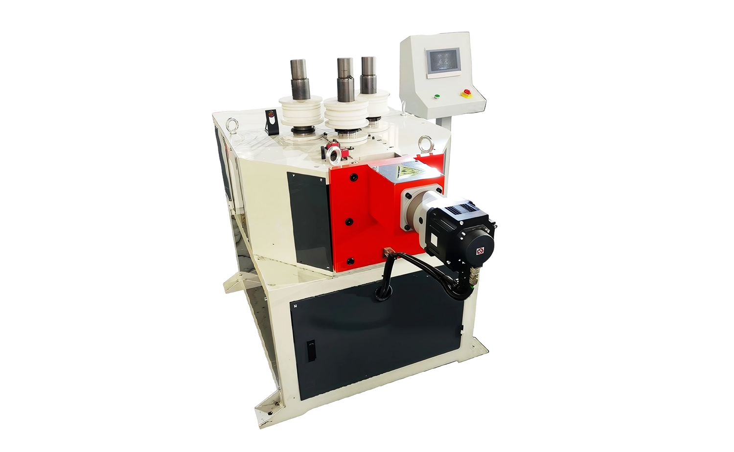
- CNC Series Tube Roll Bending Machine for Metal Profiles
- CNC Series Tube Roll Bending Machine with Three-Roller Drive
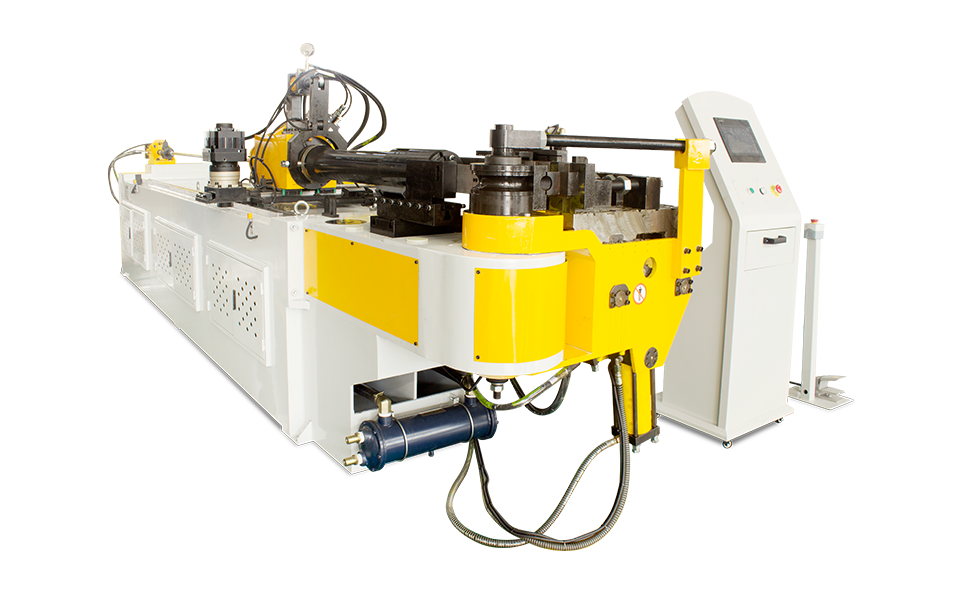
- CNC S Series Fully Automatic Tube Bending Machine with Optional Simulation Function
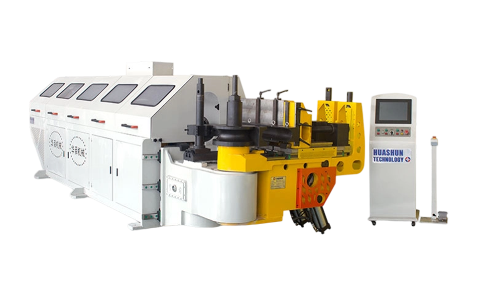
- CNC M Series Fully Automatic Multi-Radius Tube Bending Machine
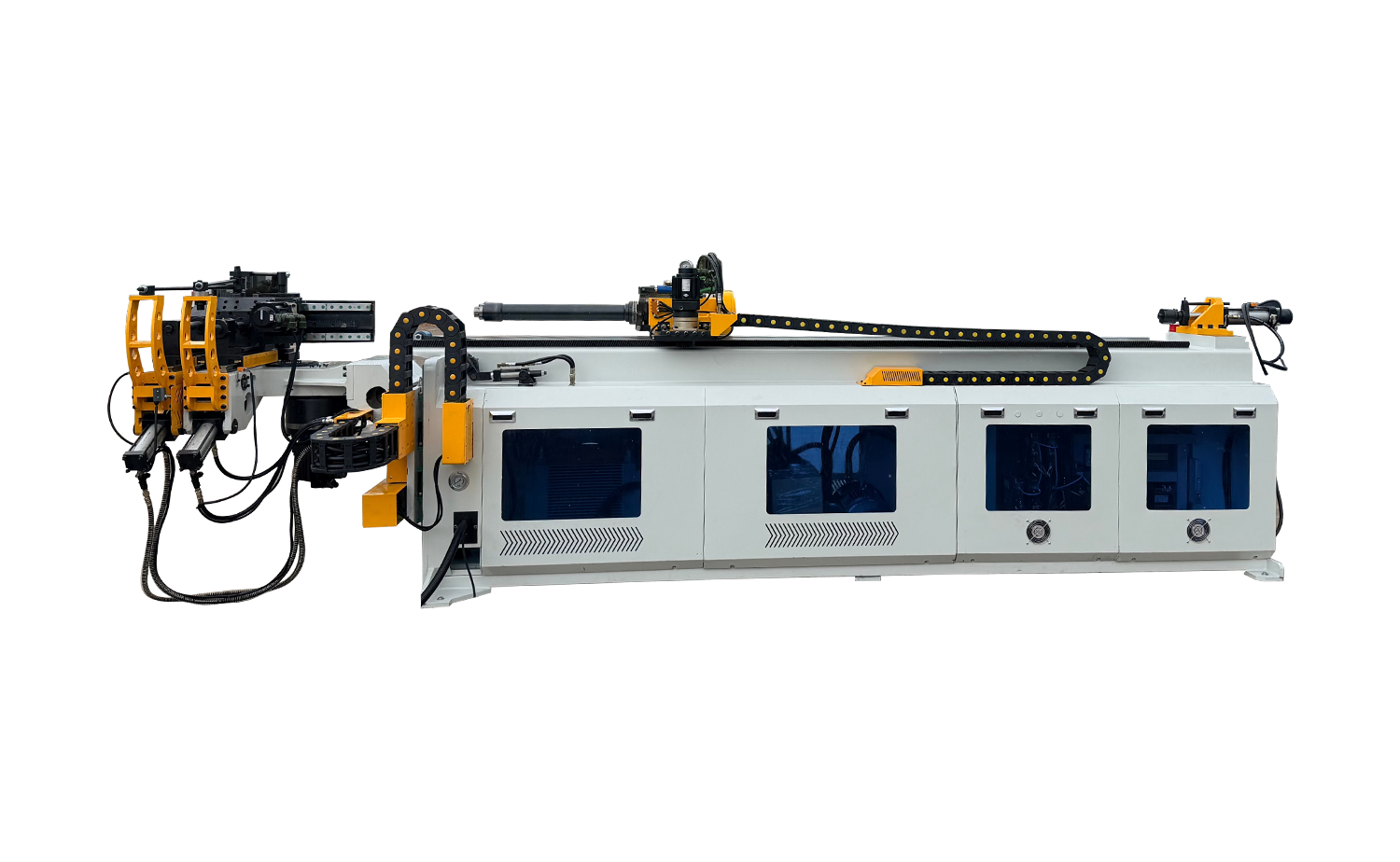
- CNC L Series Fully Automatic Tube Bending Machine with Servo-Hydraulic Control
- High Precision CNC Tube Roll Bending Machine
Why CNC Tube Bending Machines Matter for Lightweight Chassis Design?
Date:Aug 07, 2026
Content
- 1 CNC Tube Bending Technology Is a Core Enabler of Lightweight Chassis Design
- 2 Why Chassis Engineers Are Shifting Toward Tubular, Thin-Wall Structures
- 3 Material Behavior and Its Effect on Bending Strategy
- 4 How Multi-Axis Servo Control Improves Repeatability
- 5 Common Chassis and Structural Applications
- 6 Reference Technical Parameters for Servo-Hydraulic CNC Bending Equipment
- 7 Mandrel Lubrication and Long-Term Process Stability
- 8 Where This Technology Is Heading in Chassis Manufacturing
CNC Tube Bending Technology Is a Core Enabler of Lightweight Chassis Design
CNC tube bending machines make lightweight chassis manufacturing possible by shaping thin-wall, high-strength tubing into precise structural forms without cracking, wrinkling, or losing wall thickness consistency. As chassis engineers replace stamped steel panels and solid bars with hollow tubular sections made from aluminum alloys and advanced high-strength steel, the bending process becomes the point where dimensional accuracy either holds or fails. A machine capable of controlling bend angle, springback, and radius consistency across thousands of cycles determines whether a tubular subframe or crash rail actually performs as the design intended. Wall thickness reduction of even 0.3 to 0.5 mm on a structural tube can translate into several kilograms saved per vehicle, which is why bending precision has moved from a secondary concern to a primary design constraint.
Key insight: A half-millimeter of wall thickness saved on a single structural tube seems small in isolation, but multiplied across the full network of chassis, thermal, and subframe tubing in a vehicle, this precision-driven material saving becomes a measurable contributor to overall vehicle mass reduction.
Why Chassis Engineers Are Shifting Toward Tubular, Thin-Wall Structures
Traditional chassis components such as subframes, cross members, and suspension links were historically built from solid rod stock or welded steel plate. These designs are heavy relative to the load they carry because material sits in areas that contribute little to bending or torsional stiffness. Hollow tube sections distribute material toward the outer surface, where it resists bending stress far more efficiently than material near the neutral axis. This geometric advantage allows engineers to remove mass while maintaining or even improving stiffness, provided the tube can be formed into the required shape without deforming the cross-section.
This is where forming equipment becomes decisive. A tube that ovalizes during bending, or develops wall thinning on the outer radius, loses much of the structural benefit it was chosen for. Mandrel-supported CNC bending addresses this by inserting a flexible or ball-type mandrel inside the tube during the bend, preventing the cross-section from collapsing and keeping wall thickness variation within a tight band. For chassis applications, this level of control is what allows tubing to replace heavier solid sections in the first place.
Material Behavior and Its Effect on Bending Strategy
Aluminum Alloys and Springback Compensation
Aluminum tubing, particularly 6000-series alloys used in crash rails and battery enclosure frames, has a lower modulus of elasticity than steel, which means it springs back further after the bending force is released. CNC systems compensate by overbending the tube by a calculated margin, calibrated per alloy temper and wall thickness, so the finished part settles at the correct angle after the material relaxes. Without programmable angle compensation, batches of aluminum tubing would show inconsistent geometry from one part to the next.
High-Strength and Advanced High-Strength Steel
Advanced high-strength steel grades used in crash-critical members resist deformation more strongly, which raises the load the bending head must apply and increases the risk of surface cracking at the outer bend radius if feed speed and rotation are not synchronized correctly. Servo-driven feeding and rotation axes allow the bend rate to be matched to the material's strain rate sensitivity, reducing microcracking and preserving the fatigue life of the finished chassis member.
How Multi-Axis Servo Control Improves Repeatability
Chassis production runs typically require thousands of identical parts, and even small deviations in bend angle compound across multiple bends on a single tube. A three-dimensional subframe tube might require six or more bends in different planes, and an error of half a degree on an early bend can shift the final mounting point by several millimeters by the time the tube reaches its last bend. Programmable servo axes for feeding, rotation, and bending angle keep each bend within a narrow tolerance band, and the program can store the exact sequence so that every part produced on a given day matches the part produced weeks earlier.
Touch-screen PLC interfaces also let process engineers store separate programs for different tube geometries, so a single machine can switch between a suspension arm profile and a battery frame rail without manual recalibration. This flexibility matters in chassis manufacturing environments where model variants and trim levels multiply the number of distinct tube shapes needed on the same production floor.
Key insight: On a tube requiring six sequential bends, a half-degree deviation on the first bend does not stay isolated. It carries forward through every downstream bend, so the mounting point at the far end of the tube can drift by several millimeters if the early axes are not held to tight tolerance.
Common Chassis and Structural Applications
Tubular bending applies across a wide range of chassis-related components, each with its own tolerance and material demands. The table below outlines typical parts and the bending considerations associated with each.
| Component | Typical Material | Key Bending Concern |
|---|---|---|
| Subframe rails | High-strength steel | Cross-section retention under multiple bends |
| Crash rails and side members | Aluminum alloy | Springback compensation and radius consistency |
| Battery enclosure frames | Aluminum or stainless steel | Thin-wall stability and sealing surface flatness |
| Suspension links and arms | Medium-carbon or alloy steel | Angle repeatability under fatigue loading |
| Exhaust and cooling loop tubing | Stainless steel | Wall thinning resistance at tight radii |
Reference Technical Parameters for Servo-Hydraulic CNC Bending Equipment
Chassis-grade tube bending equipment generally combines hydraulic force delivery with servo-controlled feeding and rotation, giving it the load capacity needed for thicker structural tube alongside the positioning accuracy needed for repeatable geometry. A representative parameter set for this class of fully automatic CNC tube bending machine, commonly referred to as an L Series configuration with servo-hydraulic control, is shown below.
| Parameter | Specification |
|---|---|
| Mild Steel Capacity | 219 × 16 mm wall |
| Stainless Steel Capacity | 219 × 6.0 mm wall |
| Max. Rectangular Pipe | 150 × 10 mm wall |
| Max. Bending Radius | 1000 mm |
| Max. Bending Angle | 190° |
| Max. Effective Mandrel Length | 4000 mm |
| Bending Accuracy | ±0.15° |
| Bending Speed | 10 mm/s |
| Feeding Accuracy | ±0.1° |
| Feeding Speed | 300 mm/s |
| Rotation Accuracy | ±0.1° |
| Rotation Speed | 100 mm/s |
| Max. Bending Radius Difference | 150 mm |
The dual bending mode found on this class of equipment, switching between hydraulic pipe bending for standard production and servo-controlled CNC bending for complex multi-plane geometry, gives a single machine the range to cover both simple round tube parts and the intricate three-dimensional shapes found in modern chassis subassemblies. A hydraulic pressure die assist stabilizes the tube during each cycle, which helps maintain bend quality even as wall thickness and material grade vary across a production schedule.
Mandrel Lubrication and Long-Term Process Stability
Friction between the mandrel and the interior tube wall is one of the more overlooked factors in bending quality. As the mandrel slides through the tube during each cycle, insufficient lubrication increases drag, which can cause surface scoring on the inner wall and inconsistent bend force from one part to the next. A mandrel lubrication system applies lubricant directly at the contact point, reducing wear on both the mandrel and the tube surface while keeping bending force stable across a full production shift. This matters for chassis parts that later undergo welding or coating, since inner-wall surface defects can affect weld penetration or corrosion resistance at the joint.
A centralized greasing system extends this reliability to the machine's moving joints, feed carriage, and rotation bearings, reducing the frequency of manual maintenance intervention. Combined with a cooling fan in the electrical cabinet that keeps servo drives and control electronics within their operating temperature range, these systems support consistent output over long production runs without gradual drift in bending accuracy.
Key insight: Inner-wall scoring from poor mandrel lubrication is easy to overlook because it sits inside the tube and is not visible after the part leaves the machine, yet it can quietly reduce weld quality or corrosion resistance at joints further down the assembly line.
Where This Technology Is Heading in Chassis Manufacturing
As battery-electric platforms redesign chassis architecture around a flat battery pack and dedicated crash structures, tube-based frame elements are appearing in areas that previously used stamped steel assemblies. This shift places additional demand on bending equipment to handle mixed material batches, thinner walls, and tighter tolerance bands within the same production line. Touch-screen programming with stored part recipes, combined with simulation functions that preview a bend sequence before the physical cycle runs, allows engineers to validate tube geometry digitally and catch collision or springback issues before material is committed to the process. This kind of process planning is becoming a standard part of how tubular chassis components move from design to production floor.



Copyright © 2025 Huashun Technology All Rights Reserved.
Custom Precision Tube Forming Machine Manufacturers