
 English
 русский
 Español
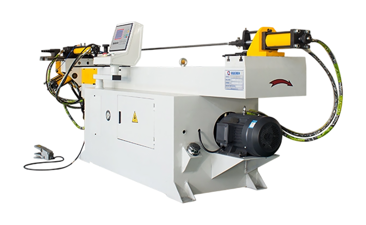
- NC S Series Mandrel Hydraulic Tube Bender with Easy-Program Setting
- DEF80CNC Series High Stability Servo Tube Chamfering Machine
- GY S Shape Series Round Tube Rolling Machine
- EF PV1 Series Hydraulic Semi-Automatic Tube Chamfering Machine
- EF PV2 Series Single Head Tube Chamfering Machine for Metal Tubes
- EF AC Series High Precision Single Head Tube Chamfering Machine
What Is Chiller Tube Punching?
Date:May 27, 2026
Content
- 1 Why Chiller Tubes Fail: Root Causes
- 2 Tube Leak Detection Methods
- 3 The Chiller Tube Punching Process
- 4 Types of Chiller Tube Plugs
- 5 Tube Punching vs. Alternative Remediation Strategies
- 6 Performance Impact of Tube Plugging
- 7 Water Chemistry Control & Prevention
- 8 Safety, Standards & Compliance
- 9 Planned Maintenance Integration & Asset Management
Chiller tube punching — also referred to as tube plugging, tube plugging by mechanical punching, or condenser/evaporator tube isolation — is a corrective maintenance procedure performed on the shell-and-tube heat exchangers found in centrifugal, screw, and absorption chillers. When individual tubes within the evaporator or condenser bundle develop leaks, cracks, pitting, or through-wall corrosion, the procedure involves permanently sealing the affected tube at both its inlet and outlet tube sheet faces using precision-machined metal plugs driven or threaded into position.
The term "punching" specifically refers to the mechanical driving action used in one of the two primary plug installation methods: tapered metal plugs are hammered or press-driven into the tube end, causing the plug to expand radially and create a pressure-tight seal against the inner tube wall. This distinguishes the method from threaded or friction-fit plugging approaches, though all variants are encompassed within the broader category of chiller tube plugging maintenance.
The procedure is performed without removing the tube bundle from the chiller shell — a critical operational advantage. Technicians access the tube ends at the water box end covers, removing the cover plates to expose the tube sheet face. The entire procedure on a single defective tube typically takes 15 to 45 minutes, making it one of the highest-value corrective maintenance interventions available for chiller plant operators dealing with heat exchanger degradation.
4–8%Efficiency loss per leaking tube
15 minAvg. plug time per tube
10%Max tubes pluggable (rule of thumb)
95%Cost saving vs. bundle replacement
Why Chiller Tubes Fail: Root Causes
Understanding the failure mechanisms that necessitate chiller tube punching is essential for both corrective maintenance and the preventive programmes that extend tube bundle life. Heat exchanger tubes in chillers operate in a demanding environment: continuous fluid flow, thermal cycling, mechanical vibration, and water chemistry fluctuations all contribute to tube wall degradation over time.
Pitting corrosion
The most common cause of chiller tube failure in copper and copper-alloy tube bundles is pitting corrosion — a highly localised electrochemical attack that produces deep, narrow cavities penetrating the tube wall. Pitting is driven by chloride ions in the condenser water circuit, dissolved oxygen concentration differentials, microbiologically influenced corrosion (MIC), and carbon film deposits left by drawing lubricants during tube manufacture. Once a pit reaches the tube's inner wall, refrigerant or water cross-contamination begins.
Erosion-corrosion
High water velocities, particularly at tube inlets where turbulence is greatest, cause erosion-corrosion — a synergistic attack where the mechanical removal of the protective oxide layer by flowing water exposes fresh metal surface to chemical attack. Inlet erosion is often visible as a horseshoe-shaped thinning of the tube wall within the first 50–100 mm of the tube inlet. Improperly designed inlet ferrules or missing flow straighteners accelerate this failure mode.
Stress corrosion cracking
Admiralty brass and certain copper-nickel alloy tubes are susceptible to stress corrosion cracking (SCC) when simultaneously exposed to tensile stress and specific chemical species — ammonia in cooling tower water being a particularly potent initiator. SCC produces circumferential or longitudinal cracks that propagate through the tube wall with little visible surface damage, making early detection by conventional inspection methods difficult.
Galvanic corrosion
In systems where dissimilar metals are present in the water circuit — copper tubes with steel or cast iron water boxes, or mixed-metal heat exchangers — galvanic corrosion accelerates attack on the less noble metal. Improper chemical treatment, inadequate dielectric isolation, and stray current effects from building electrical systems all contribute to galvanic tube degradation.
Mechanical damage and vibration fatigue
Tube-to-baffle wear, where tubes oscillate against support baffles under flow-induced vibration, progressively wears through the tube wall at contact points. Hydraulic transients — water hammer events from rapid valve closure — can cause sudden tube deformation or joint failure at the tube-to-tube-sheet roll expanded connection.
Pitting Corrosion
Localised electrochemical attack driven by chlorides, dissolved oxygen differentials, and MIC. Most common failure mode in copper-alloy tube bundles.
Erosion-Corrosion
High-velocity inlet turbulence removes the protective oxide layer, exposing fresh metal. Produces characteristic horseshoe-pattern thinning at tube inlets.
Stress Corrosion Cracking
Ammonia-driven cracking of brass and copper-nickel tubes under tensile stress. Propagates through-wall with minimal surface indication.
Vibration Fatigue
Flow-induced oscillation causes progressive tube-to-baffle wear. Water hammer events produce sudden deformation at tube-sheet roll connections.
Tube Leak Detection Methods
Accurate identification of the specific tubes requiring punching is a prerequisite for effective chiller tube maintenance. Several detection techniques are available, each with different sensitivity levels, deployment requirements, and cost implications.
Helium leak testing
Helium leak testing is the most sensitive tube leak detection method available, capable of locating leaks at rates as low as 10⁻⁶ mbar·L/s. The chiller is isolated and dewatered; the refrigerant side is pressurised with a helium-nitrogen tracer gas mixture; and a mass spectrometer detector probe is passed along the tube sheet face on the water side. The technique identifies not only which tube has failed but also the approximate axial location of the leak within the tube length — information that influences the decision between plugging and tube replacement.
Eddy current testing (ECT)
Eddy current testing is the standard non-destructive examination (NDE) technique for comprehensive tube bundle condition assessment. A probe carrying an alternating current coil is inserted through each tube; changes in the eddy current field induced in the tube wall reveal wall thinning, pitting, cracks, and corrosion deposits. ECT does not require the tube to be leaking to detect degradation — it maps the remaining wall thickness along the entire tube length, enabling predictive identification of tubes that have not yet failed but are approaching the end of their serviceable life.
Fluorescent dye tracer
For chillers where refrigerant contamination of the condenser water has been identified — typically by the appearance of foaming in the cooling tower basin or refrigerant odour in the mechanical room — fluorescent dye tracer testing localises the leak. Dye is introduced into the refrigerant circuit; UV lamp inspection of the water-side tube sheet face and water box reveals fluorescent residue at the leaking tube entry point.
Hydrostatic pressure testing
Individual tube testing by hydrostatic pressure — plugging one end and pressurising the tube with water while monitoring for pressure decay — is a reliable, low-technology method for confirming which tubes are defective once the approximate location has been narrowed by other means. It is commonly used to verify tube integrity after plugging, confirming that the plug installation has achieved a leak-tight seal.
"Eddy current testing performed as part of a planned maintenance programme transforms tube punching from a reactive emergency repair into a precision, scheduled intervention — enabling operators to address failing tubes before refrigerant loss occurs and before efficiency degradation compounds across multiple units."
The Chiller Tube Punching Process
TUBE PUNCHING PROCEDURE — SEQUENTIAL STAGES
1
Isolation & Lockout / Tagout
2
Water Box Draining & Cover Removal
3
Tube Identification & Marking
4
Plug Selection & Installation
5
Pressure Test & Return to Service
- Isolation, Lockout/Tagout & Refrigerant Safety The chiller must be fully isolated from both the chilled water and condenser water circuits before water box access. Lockout/tagout (LOTO) procedures are applied to all isolation valves, the chiller compressor, and electrical supply. If the tube leak has resulted in refrigerant migration into the water circuit, refrigerant recovery procedures must be completed before opening the water box. Confined space entry protocols apply if the water box volume meets the applicable threshold.
- Water Box Draining and End Cover Removal The water box is drained and the end cover gasket face cleaned. Both the front (inlet) and rear (outlet) end covers are removed to provide access to both ends of the defective tube. On large chillers with multi-pass water circuits, the pass partition plate arrangement must be documented before removal to ensure correct reassembly. The tube sheet face is visually inspected for general corrosion, deposit accumulation, and any additional failed tubes not previously identified.
- Defective Tube Identification and Mapping The specific tube(s) to be plugged are identified by cross-referencing the tube sheet face with the test results. A tube sheet map — a grid diagram recording the row and column position of each tube — is completed to document which tubes are being plugged and their leak severity as recorded by eddy current or pressure testing. This record is retained in the chiller's maintenance history file for future reference and for calculating cumulative plug percentage.
- Plug Selection and Mechanical Installation Plugs are selected to match the tube bore diameter, tube material, and operating pressure class. The tube bore is cleaned of scale and debris using a tube brush. For driven tapered plugs (the "punching" method): the plug is positioned at the tube end, and a plug driver tool — either a hand hammer-driven punch or a pneumatic plug installer — is used to drive the tapered plug to the specified insertion depth. The taper causes radial expansion, generating a compressive interference fit against the tube inner wall. This process is repeated at the opposite tube end. For threaded plug systems, a thread tap is first used to cut internal threads at the tube end, and the threaded plug is torqued to the manufacturer's specification using a calibrated torque wrench.
- Post-Installation Pressure Testing and Recommissioning Following plug installation at both tube ends, the water box is reassembled with a new gasket and hydrostatic pressure tested to at least 1.5× the design working pressure to confirm plug integrity. The chiller is then recommissioned: water circuits are refilled and vented, refrigerant charge is verified, and a supervised startup is performed. Post-startup performance monitoring — comparing approach temperatures, compressor power, and capacity against pre-maintenance baseline data — confirms that the repair has restored expected heat exchanger performance.
Types of Chiller Tube Plugs
The selection of the correct plug type for a specific chiller tube punching application is determined by tube bore diameter, operating pressure, tube material, and the nature of the sealing environment. Three primary plug designs are used in chiller applications.
| Tapered Mechanical Plugs | Solid metal plugs with a tapered body driven into the tube bore. Available in copper, brass, stainless steel, and titanium to match tube material. The interference fit between plug and tube wall creates the pressure seal. Installation is fast and requires no specialised threading preparation. |
| Threaded Plugs | Machined plugs that engage internal threads tapped into the tube end. Provide a higher integrity seal than driven plugs and are preferred for high-pressure applications or where vibration may loosen a friction-fit plug. Require thread-tapping tooling and greater installation time. |
| Explosive / Hydraulic Expansion Plugs | Plugs installed by hydraulic pressure or controlled explosive charge that causes the plug body to expand radially against the tube wall. Used where conventional mechanical driving is impractical due to tube geometry or access constraints. Widely used in power station condenser tube plugging — less common in HVAC chiller applications. |
| Silicone / Rubber Plugs (Temporary) | Friction-fit elastomeric plugs used as temporary seals during leak testing or commissioning. Not rated for permanent service in pressurised chiller applications — must be replaced with metal plugs before return to service. |
| Material Matching | Plug material must be compatible with both the tube material and the water chemistry to prevent galvanic corrosion at the plug-tube interface. Copper plugs for copper tubes; stainless or titanium for stainless or titanium bundles. Mismatched plug materials accelerate adjacent tube attack. |
Material Compatibility Warning
Never install copper or brass plugs in stainless steel or titanium tube bundles, and do not use steel plugs in copper tube applications. Galvanic potential differences at the plug-to-tube interface will accelerate corrosion of the adjacent tube wall and tube sheet, converting a single-tube defect into a multi-tube failure zone within one to two operating seasons.
Tube Punching vs. Alternative Remediation Strategies
Chiller tube punching is one of several remediation options available when heat exchanger tube failures are identified. The optimal strategy depends on the number and severity of failed tubes, the age and condition of the tube bundle, and the operator's long-term asset plan for the chiller.
| Strategy | Tube Punching / Plugging | Individual Tube Replacement | Full Bundle Re-tubing | Chiller Replacement |
|---|---|---|---|---|
| Downtime Required | Hours (half-day typical) | 1–2 days per tube | 1–3 weeks | 2–6 weeks |
| Chiller Shutdown Scope | Water box access only | Water box + shell access | Full bundle extraction | Full plant shutdown |
| Capital Cost | Very low (plugs + labour) | Low–moderate | High | Very high |
| Effect on Thermal Performance | Minor (1–2% loss per 10 plugs) | Neutral | Full restoration | Full restoration + improvement |
| Addresses Root Cause | No — isolates failed tubes only | Partial | Yes (new tube material option) | Yes |
| Suitable When | <10% of tubes failed; chiller <15 yrs | 1–3 isolated tube failures | Widespread degradation | Chiller near end of design life |
| Specialist Equipment Needed | Minimal — plug kit + hammer | Tube puller + roller expander | Full workshop mobilisation | Crane, rigging, new equipment |
| On-site Execution Feasibility | Yes — standard maintenance team | Specialist recommended | Major contractor required | Manufacturer / major contractor |
Performance Impact of Tube Plugging
Every tube plugged in a chiller heat exchanger removes a heat transfer surface from service, reducing the total active tube count available for thermal exchange. Understanding the quantitative relationship between tube plug count and chiller performance is essential for engineering decisions about when tube punching remains an acceptable remediation and when bundle re-tubing or chiller replacement becomes necessary.
Heat transfer area reduction
The heat transfer area in a shell-and-tube heat exchanger is directly proportional to the number of active tubes. Plugging 10 tubes in a bundle of 500 reduces the active heat transfer area by 2%. However, the thermal performance impact — measured as chiller coefficient of performance (COP) or approach temperature increase — is typically greater than the proportional area reduction would suggest, because the remaining tubes must work harder at elevated water velocities to transfer the same heat duty, increasing pressure drop and shifting the operating point on the compressor map.
The 10% rule and its limits
The widely cited "10% rule" — that plugging up to 10% of tubes in a bundle is acceptable without triggering re-tubing — is a useful starting guideline but not an engineering absolute. Its validity depends on whether the plugged tubes are distributed uniformly across the bundle or concentrated in specific zones (which creates flow maldistribution), on the chiller's design margin at the original specification point, and on whether the condenser or evaporator bundle is affected (condenser tube plugging has a larger performance impact than evaporator plugging in most chiller designs).
Approach temperature monitoring
The most reliable field indicator of heat exchanger performance degradation from tube plugging is the approach temperature — the difference between the refrigerant saturation temperature and the water outlet temperature on the heat exchanger. Trending the approach temperature against the plug count over successive maintenance visits provides an empirical basis for the decision to proceed with re-tubing rather than continued plugging. An approach temperature that has increased by more than 2–3°C from the design condition typically warrants a formal thermal performance analysis.
Indicators That Plugging Remains Viable
- Fewer than 8–10% of total tubes are plugged
- Chiller is fewer than 12–15 years from commissioning
- Failed tubes are randomly distributed across bundle
- Eddy current shows remaining tubes are >80% wall thickness
- Approach temperature increase is less than 2°C above design
- Chiller meets capacity requirements with remaining active tubes
- No widespread pitting pattern suggesting systemic water chemistry failure
Indicators That Re-Tubing Is Required
- Plug count exceeds 10% of total tube complement
- Clustered tube failures indicate localised corrosion attack zone
- Eddy current shows widespread wall thinning across bundle
- Approach temperature more than 3°C above design condition
- Compressor operates at elevated lift to maintain capacity
- Chiller is approaching or beyond design life
- Water chemistry failure has driven systemic tube attack
Water Chemistry Control & Prevention
The single most effective measure for minimising the frequency of chiller tube punching interventions is rigorous water treatment and chemistry management across both the condenser water (open cooling tower) and chilled water (closed loop) circuits. The majority of tube failures in copper-alloy bundles are attributable to water chemistry conditions that fall outside the manufacturer's prescribed limits.
Condenser water treatment
Open cooling tower systems concentrate dissolved minerals through the evaporation cycle, progressively raising the concentration of scale-forming ions (calcium, magnesium, bicarbonate), corrosion-inducing species (chlorides, sulphates), and biological growth potential. A properly designed water treatment programme includes corrosion and scale inhibitors dosed to maintain protective film-forming conditions, biocides for microbiological control (both planktonic and sessile organisms that drive MIC), and automatic bleed/blowdown control to maintain Langelier Saturation Index (LSI) within the range of 0 to +0.5 for copper-alloy tubes.
Chilled water loop chemistry
Closed chilled water loops are susceptible to oxygen ingress at expansion vessel interfaces and system make-up water additions. Dissolved oxygen concentrations above 0.1 ppm accelerate pitting corrosion in copper evaporator tubes. Closed-loop treatment with oxygen scavengers, film-forming corrosion inhibitors, and periodic sampling and analysis maintains protective conditions. The loop pH should be maintained between 7.0 and 8.5 for copper systems — alkaline conditions above pH 9.0 cause selective leaching of zinc from brass alloy components.
- Quarterly water analysis minimum: Test for pH, conductivity, hardness, alkalinity, chlorides, sulphates, inhibitor concentration, and microbiological counts on both circuits
- Annual eddy current inspection on chillers over 7 years old: Trending wall thickness data year-on-year enables predictive plug scheduling before leaks occur
- Inlet ferrule condition checks at every water box opening: Replace eroded or missing inlet ferrules immediately — they are the primary protection against inlet erosion-corrosion
- Verify cooling tower basin cleanliness: Sediment accumulation in the tower basin introduces abrasive particles and biological material into the condenser circuit, accelerating tube attack
- Commission a full tube bundle survey before major building tenancy changes: Changes in building occupancy alter chilled water demand patterns and system operating points, sometimes triggering flow conditions outside the original tube design parameters
Safety, Standards & Compliance
Chiller tube punching is a maintenance activity conducted on pressurised refrigerant-containing equipment — a classification that places it within the regulatory scope of multiple safety and environmental compliance frameworks depending on jurisdiction.
Refrigerant handling regulations
In the European Union, chiller maintenance activities that involve opening the refrigerant circuit or working on equipment containing F-gases are regulated under EU Regulation 517/2014 (F-Gas Regulation). Only personnel holding the applicable F-gas certification may recover, recharge, or handle the refrigerant. In the United States, EPA Section 608 of the Clean Air Act mandates that refrigerant not be intentionally vented to atmosphere and that recovery be performed by certified technicians. Tube punching itself does not require opening the refrigerant circuit — it is conducted entirely on the water side — but if refrigerant contamination of the water circuit is confirmed, refrigerant recovery from the affected water volume may be required before water box opening.
Pressure vessel and confined space regulations
Chiller shells and water boxes are classified as pressure vessels under applicable standards (PED 2014/68/EU in Europe; ASME Section VIII in the US). Any maintenance activity that involves opening pressure boundary components — including water box end covers — must follow documented procedures and, in many jurisdictions, be performed or supervised by competent persons as defined by the applicable pressure vessel regulation. Water boxes of large chillers may meet the definition of confined spaces under occupational health and safety regulations, requiring confined space entry permits, atmospheric testing, and rescue provisions.
Documentation requirements
A complete maintenance record for each chiller tube punching intervention should include the date and technician identification, the tube sheet map showing plug locations, the plug type and material used, the hydrostatic pressure test result and pressure rating, the eddy current or other diagnostic data that prompted the intervention, and the post-maintenance performance data. This documentation supports asset management decisions, warranty claims, and regulatory compliance audits.
Regulatory Note
In jurisdictions with F-gas or refrigerant handling regulations, always confirm whether the tube leak has resulted in refrigerant contamination of the water circuit before opening the water box. If refrigerant is detected in the water, initiate refrigerant recovery procedures and engage a certified refrigerant handling technician before proceeding with tube punching operations.
Planned Maintenance Integration & Asset Management
Integrating chiller tube punching within a structured planned maintenance programme — rather than responding reactively to refrigerant leaks and chiller shutdowns — transforms the procedure from an emergency repair into a predictable, budgeted, and efficiency-preserving maintenance activity.
Maintenance trigger framework
The optimal trigger for scheduled tube punching is an eddy current survey result showing one or more tubes with remaining wall thickness below 80% of nominal — the typical acceptance threshold used by chiller manufacturers and the American Society of Heating, Refrigerating and Air-Conditioning Engineers (ASHRAE). Tubes at or below this threshold are at high statistical risk of through-wall failure within one to two operating seasons. Scheduling a water box opening and targeted plugging based on eddy current findings prevents the uncontrolled refrigerant release events that result from operating degraded tubes to failure.
Lifecycle plug count tracking
Every plug installation should be recorded in the chiller's maintenance history alongside the tube identification number (row, column, bundle position) and the reason for plugging (eddy current finding, confirmed leak, precautionary). Cumulative tracking of the plug count against total tube complement enables the facilities management team to identify the trajectory toward the re-tubing decision threshold and plan accordingly — avoiding the scenario where an emergency re-tubing is required during peak cooling season with no budget provision.
Coordination with chiller overhaul cycles
On chillers subject to periodic major overhauls — typically every 5 to 7 years for large centrifugal units — tube punching maintenance should be coordinated with the overhaul window to minimise total chiller downtime. Eddy current surveys conducted as part of the overhaul scope provide a comprehensive bundle condition baseline from which the next 5-year tube punching requirement can be projected with reasonable accuracy. This forward-looking approach eliminates unplanned water box openings between overhaul cycles and supports capital maintenance budgeting for the full asset management plan.
- Schedule eddy current surveys every 3–5 years: Annual surveys are cost-justified on chillers with known water chemistry problems or bundles over 10 years old
- Maintain a tube sheet map for every chiller: Update the map at each water box opening — the cumulative plug distribution pattern often reveals systemic attack zones that should prompt a water chemistry investigation
- Budget plug materials as a standing spare: Keep a supply of plugs in the correct bore diameter and material for each chiller on-site; emergency procurement delays extend unplanned shutdown duration unnecessarily
- Set a re-tubing trigger at 8–10% cumulative plugs: Commission a formal thermal performance analysis and re-tubing cost estimate when the plug count reaches 8% — allowing time for procurement and scheduling before the 10% threshold forces the decision
- Include tube condition in chiller plant energy audits: The approach temperature increase attributable to plugging and fouling often represents 5–15% of total chiller energy cost — quantifying this provides the business case for investment in bundle maintenance
In summary: Chiller tube punching is one of the most cost-effective and operationally efficient maintenance interventions available to chiller plant operators. By identifying failing tubes through systematic eddy current inspection and isolating them with precision metal plugs before refrigerant loss occurs, facilities teams preserve chiller efficiency, avoid unplanned downtime, and extend heat exchanger bundle life by years. The technique's value is greatest within a structured preventive maintenance framework — where water chemistry management minimises tube attack rates, regular inspection provides early warning of degradation, and plug installations are documented, tracked, and managed against a clear threshold for the eventual bundle re-tubing decision.


Copyright © 2025 Huashun Technology All Rights Reserved.
Custom Precision Tube Forming Machine Manufacturers