
 English
 русский
 Español
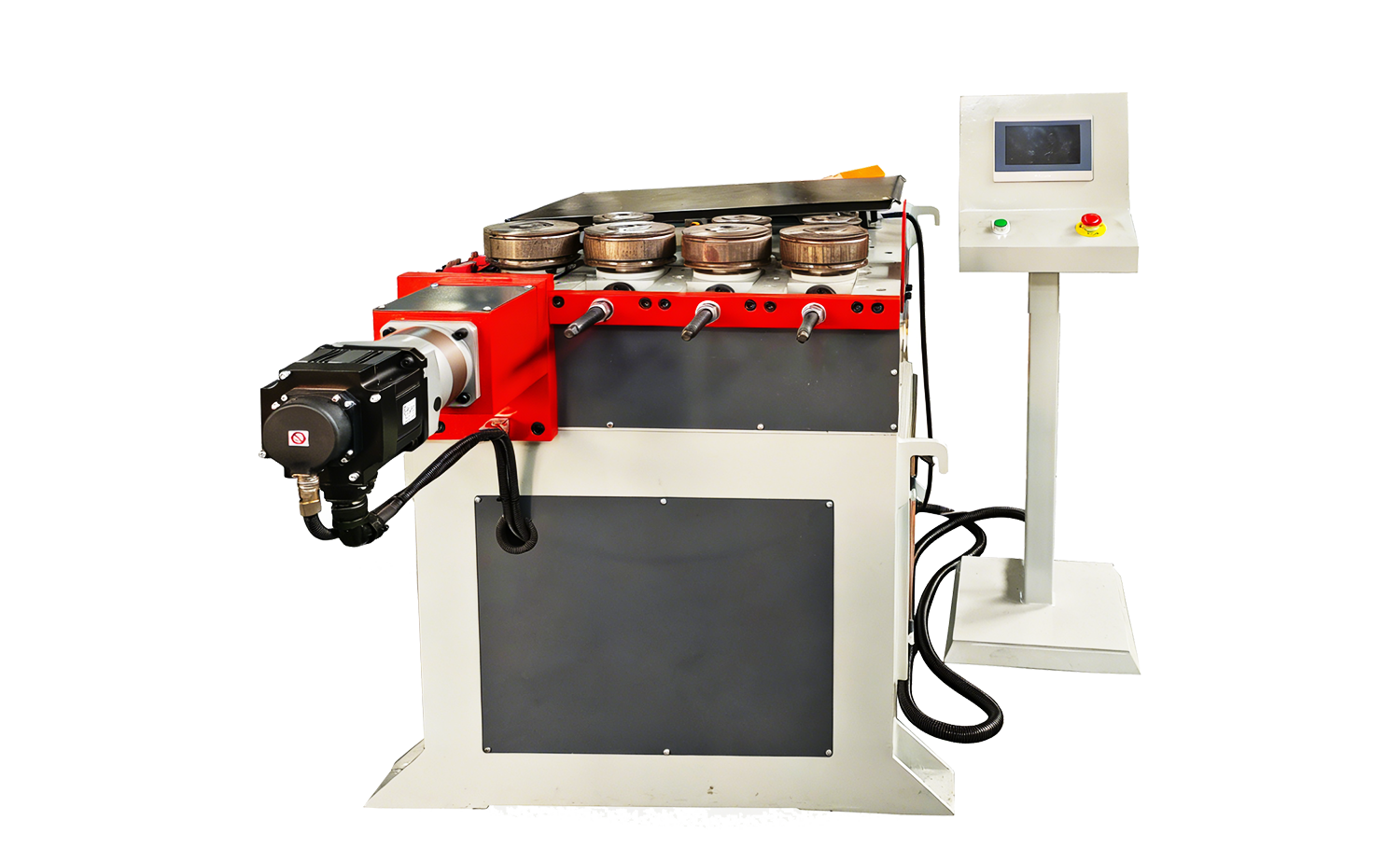
- High Precision CNC Tube Roll Bending Machine
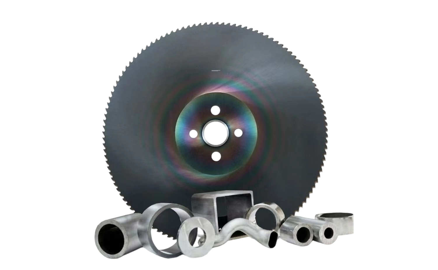
- High-Precision Tube Cutting Saw Blade
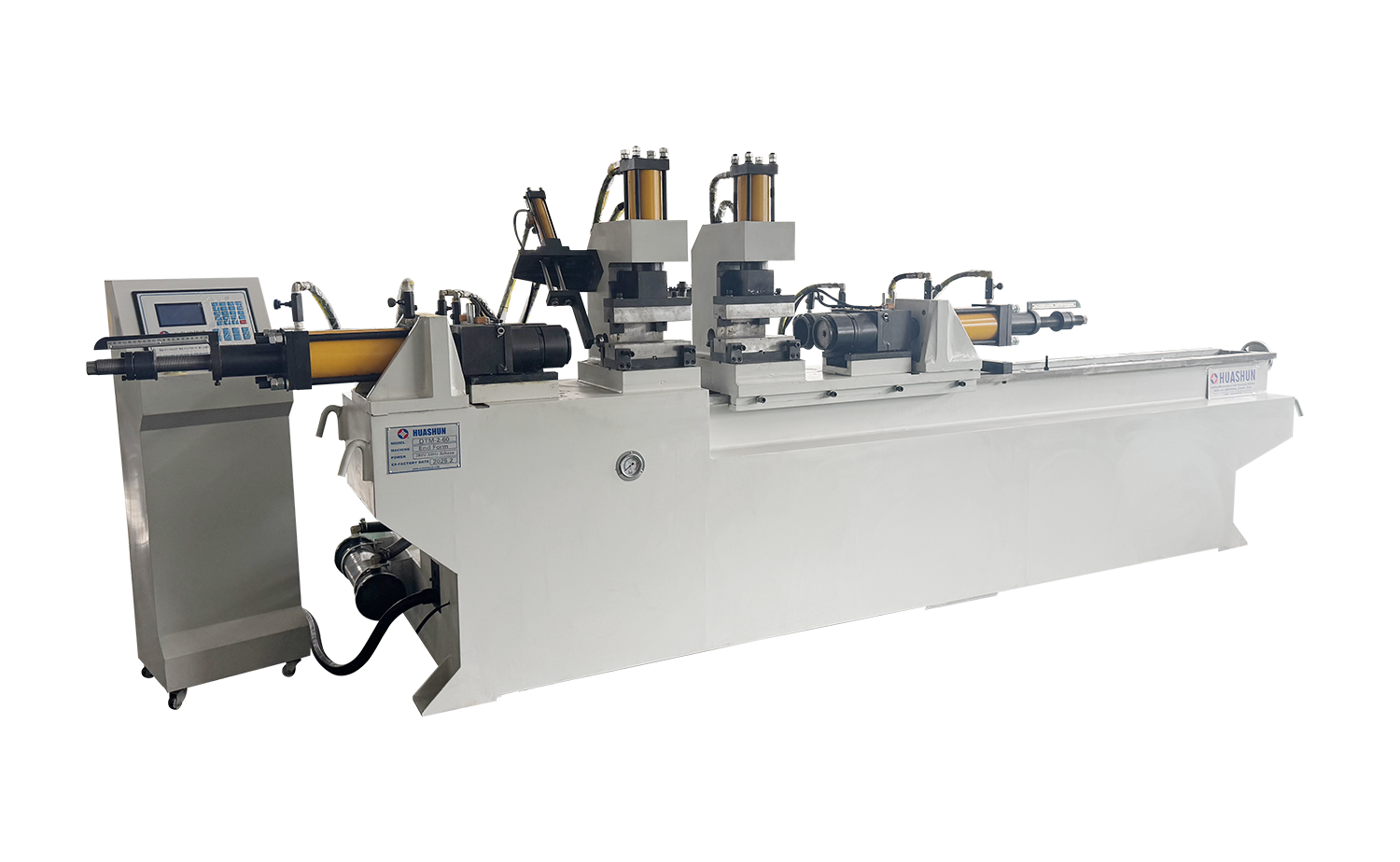
- DTM40 High Efficiency Double Head Hydraulic Tube End Forming Machine
- GY40 CNC Series High-Speed Thin-Walled Tube Roll Bending Machine
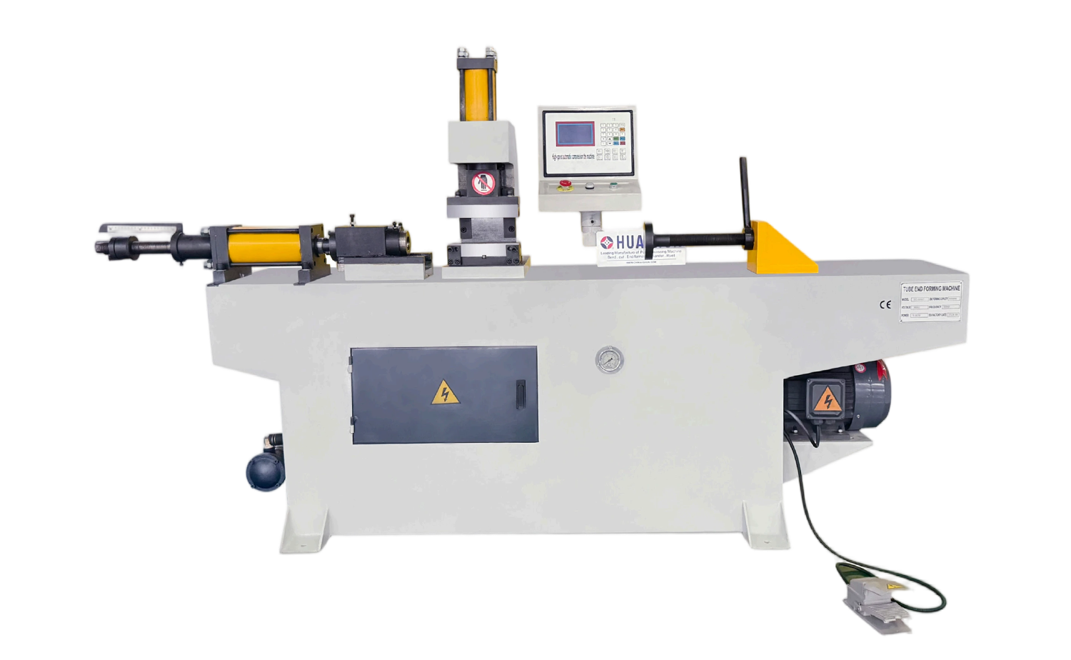
- TM40 High Efficiency Automatic Single Head Tube End Forming Machine
- DEF80CNC Series High Stability Servo Tube Chamfering Machine
High Tolerances in Tube Fabrication: Practical Notes from the Shop Floor
Date:Nov 06, 2026
Content
- 1 What High Tolerances Really Mean
- 2 Where Tight Windows Actually Earn Their Keep
- 3 Cutting: Where Tolerance Is Won or Lost First
- 4 Bending: Springback, Mandrel, and the Angle You Asked For
- 5 End Forming and Chamfering: Small Features, Tight Expectations
- 6 Reading a Callout Without Over-Engineering
- 7 Habits That Hold High Tolerances Day After Day
- 8 Questions We Hear Most Often
Tolerance is one of those words that quietly changes meaning depending on who is holding the drawing. A designer says "high tolerances" and means a narrow window around a nominal dimension. An operator on the floor hears the same phrase and immediately thinks about springback, tool wear, and whether this morning's material will behave like last week's batch. Both readings are correct, and the gap between them is where most tube fabrication problems are born.
We have spent a lot of years building and supporting tube processing equipment, and the conversations we enjoy most are the ones where a customer brings a drawing, a sample, and a genuine question: can we actually hold this, run after run, without paying for it twice? This article is our attempt to answer that question honestly.
What High Tolerances Really Mean
In everyday speech, a "high tolerance" part is one that must be made very precisely. In engineering language, the tolerance itself is the permitted deviation, so a high tolerance in the colloquial sense is actually a small number — a tight band. A tube might be specified as 25.00 mm ±0.05 mm outside diameter, which means anything between 24.95 and 25.05 mm is acceptable. Everything outside that band is scrap, rework, or a difficult phone call.
It helps to separate the ideas that often get bundled together. Dimensional tolerance covers length, diameter, and wall thickness. Geometric tolerance covers form and orientation — straightness, roundness, concentricity, and the positional relationships that GD&T symbols describe on a drawing. A part can pass every dimensional check and still fail assembly because a bend plane is rotated two degrees from where it should be. That is a geometric problem, and it is usually the expensive one.
There is also a practical distinction between process tolerance and part tolerance. A machine may be capable of ±0.05 mm on a good day with clean material, while the drawing asks for ±0.15 mm and the customer measures with a caliper at the end of the line. Understanding what is actually being verified — and with what instrument — prevents a great deal of unnecessary tooling investment.
Where Tight Windows Actually Earn Their Keep
Not every tube needs to be held to a whisker. Structural frames, handrails, and decorative arches generally live comfortably inside a millimetre or two. Tight tolerances matter when something else has to fit, seal, rotate, or be welded by a robot that does not know how to improvise.
Three situations come up again and again in our project work. The first is a mating interface: a tube end that slides into a fitting, a boss, or a mating pipe, where clearance and interference are both failures. The second is multi-bend geometry, where small angular errors accumulate along a sequence of bends until the last leg misses its bracket by several millimetres. The third is anything downstream of the tube itself — a fixture, a robot welding cell, or an automated assembly station that assumes the incoming part is where the model says it is.
| Process | Typical working window | What usually drives the variation |
|---|---|---|
| CNC tube bending (angle) | ±0.1° per bend | Springback behaviour, mandrel condition, material batch |
| CNC tube bending (length between bends) | ±0.1 to ±0.2 mm | Feed accuracy, cut length consistency, tube straightness |
| Servo-feeding tube cutting | ±0.05 mm length | Blade sharpness, clamp grip, incoming straightness |
| Laser tube cutting | ±0.05 to ±0.1 mm | Machine calibration, wall thickness, heat input |
| Tube end forming | ±0.1 mm on diameter and length | Tool wear, lubrication, material ductility |
| Chamfering and deburring | ±0.05 mm face width | Blade condition, clamping repeatability, wall variation |
Cutting: Where Tolerance Is Won or Lost First
Almost every tolerance argument downstream traces back to the cut. If the blank is 0.3 mm long, the bender will faithfully carry that error around the part, and no amount of angle correction will bring the final leg home. Servo feeding changed this conversation for us. Instead of relying on an operator to index a stop by eye, a servo axis positions the tube, measures the result, and repeats the same move thousands of times.
Blade condition deserves more respect than it usually gets. A saw blade that has cut a few thousand stainless pieces will still look serviceable while quietly pushing the burr height and length variation upward. We recommend a simple habit: keep a first-article sample, re-measure it at the start of each shift, and compare. That single practice catches most cutting drift before it becomes a batch problem.
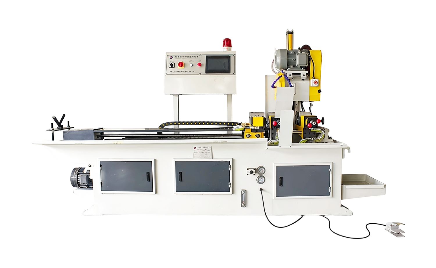 CNC Servo-Fed Automatic Tube Cutting MachinePLC-controlled servo feeding and clamping automate cutting of round, square, and solid tube profiles across industrial production.View Product →
For tube that has to arrive straight as well as short, a straightening and cutting arrangement is often a better fit than a conventional saw, particularly with long coil-fed stock.
Bending: Springback, Mandrel, and the Angle You Asked For
Every tube remembers being bent. Release the tooling and it springs partly back, and how far depends on material grade, wall thickness, heat treatment history, and the bend radius relative to the tube diameter. CNC machines handle this by storing a correction value per material, radius, and tooling set, then refining it after the first article is measured. Whether that correction stays valid depends on how disciplined the material supply is.
Wall thinning on the outside of the bend is the other quiet variable. A generous mandrel with a well-positioned wiper die keeps the inner wall supported and spreads the deformation, which is why tooling condition and high tolerances are really the same subject. When a customer tells us their bend radius tolerance has slipped, the first question we ask is not about the control system — it is about the mandrel and the last time the tooling was inspected.
Variable and multi-radius work adds a further layer. Parts that combine several radii on one tube need a machine that can hold a bend plane rotation precisely, because a small rotation error at bend two becomes a large positional error at bend five. This is exactly where a fully automatic servo-hydraulic platform pays for itself.
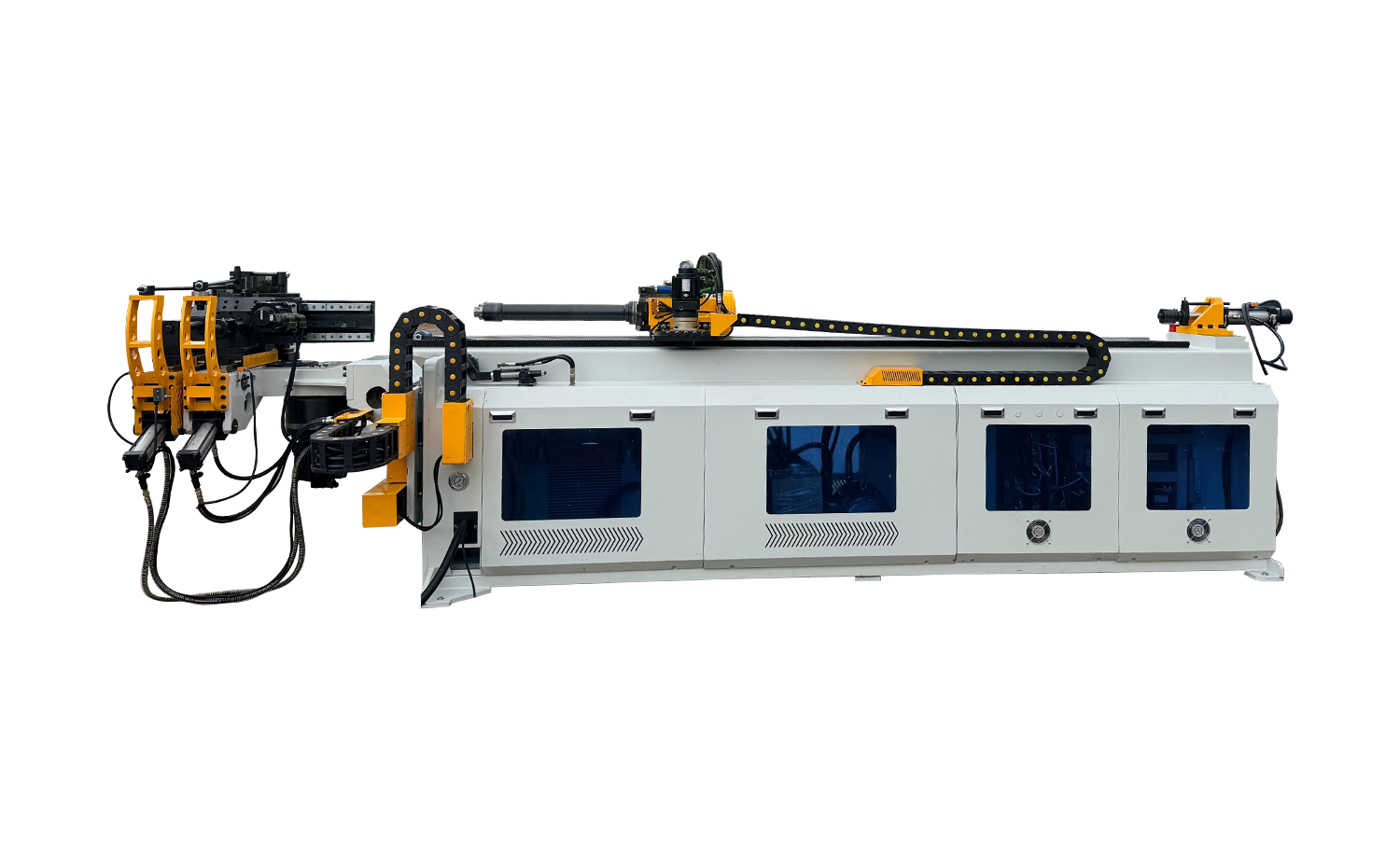 Fully Automatic CNC S Series Tube Bending MachineServo-hydraulic bending platform with programmable axes and optional simulation, suited to multi-radius tube work needing precise feeding and bend-plane rotation.View Product →
Automated inspection or a simple checking fixture should follow the same philosophy as the machine: measure the feature that participates in assembly, not just the one that is easy to reach. For automotive tube assemblies, where several bends and a bracket land all interact, that discipline is the difference between a smooth launch and weeks of adjustment.
End Forming and Chamfering: Small Features, Tight Expectations
Tube ends are where tolerances become visible. An expanded end that will not accept a hose, a chamfer that is uneven because the tube was not seated squarely, or a taper that varies around the circumference will all show up in final assembly long before anyone notices the length. Servo-controlled chamfering and hydraulic end forming give the operator repeatable depth and force, which is most of the battle.
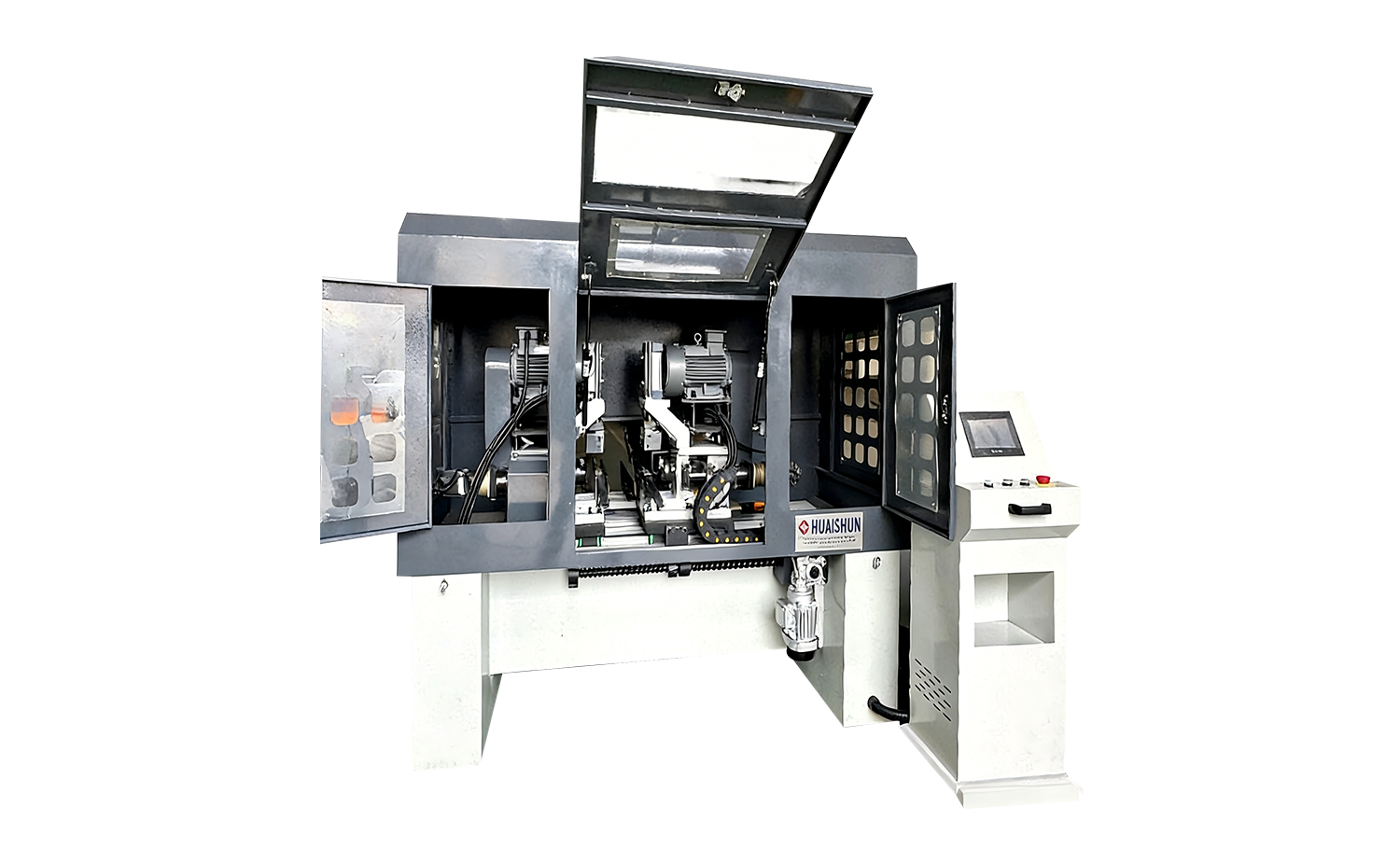 DEF80CNC High-Stability Servo Tube Chamfering MachineSemi-automatic servo-controlled chamfering for flat, internal, or external faces, with a high-precision clamp for consistent pipe and bar end preparation.View Product →
Two practical notes from our service visits: keep the cutting blades sharp enough that the tool pushes rather than tears, and check that the clamping system is gripping the tube body, not compensating for a bowed blank. A chamfer machine fed with inconsistent straightness will produce inconsistent faces, no matter how accurate its servo axis is.
Reach out to the applications page if you would like to see how this works in practice across industries such as automotive manufacturing, where the tolerance conversation is rarely optional.
Reading a Callout Without Over-Engineering
Before adding a process or a fixture, it is worth confirming what the drawing actually asks for. Most modern tube drawings use one of a small family of conventions:
- Bilateral tolerance — equal allowance above and below the nominal value, the most familiar format.
- Unilateral tolerance — all allowance on one side, common when a feature must never be larger than nominal.
- Limit dimensions — an upper and lower size listed directly, with no nominal to interpret.
- General tolerance block — a blanket rule on the drawing title block covering dimensions without individual callouts.
- Geometric controls — straightness, position, profile, and runout that describe relationships rather than sizes.
Tolerance stack-up is the next thing to check. If four features each sit inside their own window, the assembly can still fail because the errors line up in the same direction. A short stack-up calculation at the design stage is far cheaper than re-tooling a fixture after the first production run. In many cases the answer is not "make everything tighter" but "identify the one feature that actually controls the fit and tighten only that."
Habits That Hold High Tolerances Day After Day
Capability on a demonstration part and capability in month six are different claims, and the gap between them is usually maintenance and documentation rather than machine specification. A few habits seem to travel well between shops:
- Keep the material batch traceable, and re-qualify bend corrections when the heat number changes.
- Inspect tooling on a schedule, not on a hunch — mandrels, wiper dies, blades, and forming punches all wear progressively.
- Let the machine settle thermally before running a tight first article, especially on hydraulic platforms.
- Record first-article measurements and compare them shift to shift rather than part to part.
- Measure the way the customer measures, with an instrument of appropriate resolution, and agree on that method in writing.
- Treat straightness as a tolerance in its own right; it quietly affects every downstream operation.
None of this requires a metrology laboratory. It requires a routine that someone owns and a willingness to stop a run when the numbers drift.
Questions We Hear Most Often
Is a high tolerance the same as a tight tolerance?
In everyday conversation, yes — people say "high tolerance" to mean a demanding, precise part. On a drawing, tolerance is the amount of permitted variation, so a tighter specification is a smaller number. It is worth clarifying the wording early in a project, because two people can leave the same meeting with opposite impressions.
How do I know which tolerance to specify?
Work backwards from function. Identify the fit, seal, or assembly interface that must work, determine how much clearance it truly needs, and specify only the features that participate. Blanket tightening across a whole drawing raises cost quickly and rarely improves the outcome.
Can I hold tight tolerances on thin-walled tube?
Yes, with the right tooling and realistic expectations. Thin walls deflect under clamping force and spring back differently, so mandrel support, gentle clamping, and a machine with smooth servo control matter more than raw tonnage. If the wall is very thin, expect to spend more time on the first article and to review the setup whenever the material changes.
High tolerances are less a specification than a working relationship between material, tooling, machine, and the people watching the numbers. Get the first three aligned and the fourth becomes much easier. If you are working through a demanding tube part and want a second opinion on the process — cutting, bending, end forming, or chamfering — we are always happy to look at the drawing with you and say plainly what is realistic. For heat exchangers, cooling loops, and other HVAC work, the same principles hold.
Recommended Articles
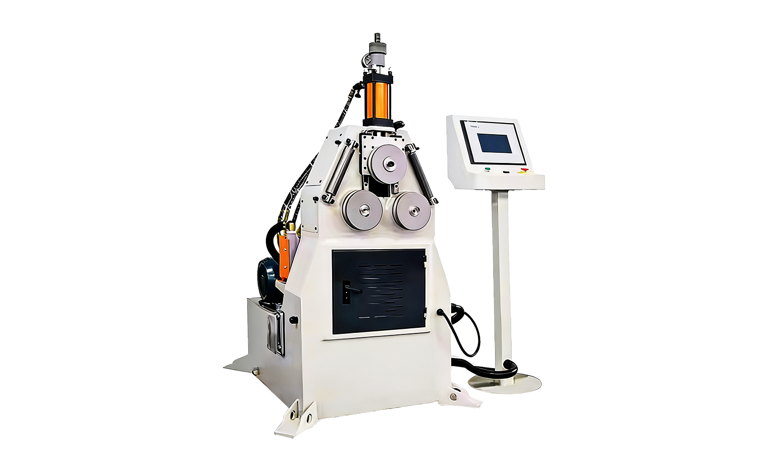


Copyright © 2025 Huashun Technology All Rights Reserved.
Custom Precision Tube Forming Machine Manufacturers